I. Overview
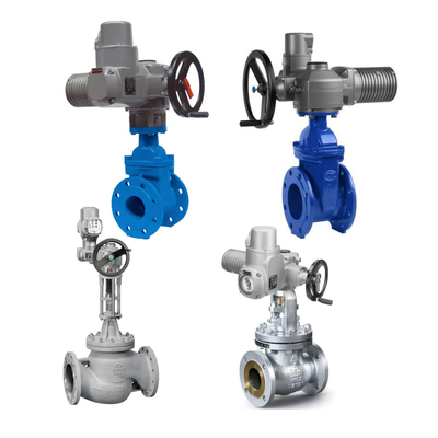
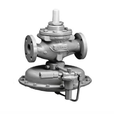
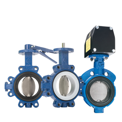
Control valve belongs to the control valve series, the main role is to regulate the flow, pressure and level of the medium. Control valves can be divided into: linear and angle stroke according to the characteristics of the trip. Straight stroke including: single seat valves, double seat valves, sleeve valves, angle valves, three-way valves, diaphragm valves; angle stroke including: butterfly valves, ball valves, eccentric rotary valves, full-featured ultra-lightweight control valves. Control valves can be divided into: pneumatic control valves, electric control valves and hydraulic control valves according to the drive mode; according to the regulating form can be divided into: regulating, cut-off type, regulating cut-off type; according to the flow characteristics can be divided into: linear, equal percentage, parabolic, fast open. Control valves are suitable for air, water, steam, various corrosive media, mud, oil and other media.

II. the principle of work
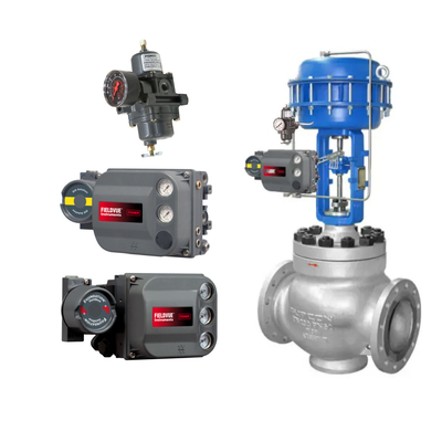
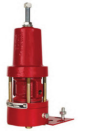
The regulating valve consists of two parts: the electric actuator (or pneumatic actuator) and the regulating valve. Among them, the actuator is the driving device of the regulating valve, which produces the corresponding thrust according to the size of the signal pressure, and the actuator produces the corresponding displacement, thus driving the spool action of the regulating valve. The valve body is the regulating part of the regulating valve, which is in direct contact with the medium, and the action of the spool changes the throttling area of the regulating valve to achieve the purpose of regulating the flow, pressure and level of the medium, and it is the final control element in the process loop.
III. equipment integrity standards
- Control valve exposed threads, valve stem and nut to keep clean, neat, all kinds of good lubrication.
- The vicinity of the valve body bracket should be clean and complete, and the bolts of each part should be complete and solid, and there should be lubrication oil and no spoils.
- Valve stem seal ring is not dirty, no leakage, import and export flange connection is secure, no leakage, no seepage.
- Valve stem lubrication is good, no corrosion.
- The regulating valve positioner is neat, no corrosion, internal neat, well lubricated.
- Feedback lever is flexible, no corrosion, lubricating oil for each part.
- The accessories of the control valve are complete, no loosening phenomenon.
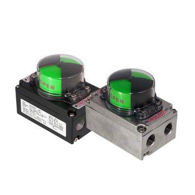
- The travel indicator of the control valve is complete, flexible, good and accurate.
- Pressure-reducing filter is clean, no damage, no air leakage.
- Electromagnetic valve is clean, no air leakage, reliable operation, and the coil is intact and not damaged.
- The signage of the control valve is clean, clear and free of corrosion.
- The control valve is flexible, smooth and accurate.
IV. the control valve overhaul preparation
- The control valve valve positioner, filter, solenoid valve, holding valve, pneumatic amplifier and other accessories of the signal interface, media flow labeling records. With a digital camera on the valve as a whole, the valve with the important accessories, valve failure points, signs, important connections from multiple angles to take pictures, and save the picture number properly!
- control valves were disconnected from the power, gas check the valve failure status, make a good record
- For the angular stroke valve should be written down the direction of rotation of the valve (generally clockwise off the valve, counterclockwise open the valve), so as to avoid mistakes in the maintenance, the wrong valve accident way, the installation of careless damage to the return switch, etc.
- In the cabinet or on-site junction box, remove the valve control, signaling and other signaling line terminals, cable head wrapped in insulating tape
- Close the ball valve of gas source, remove the gas source wind line, and completely drain the instrument wind in the actuator.
- Seal the air interface
- Determine whether to dismantle the valve positioner, filtering and pressure reducing valve, holding valve, pneumatic directional valve, amplifier, air line pipe and other accessories according to the type of maintenance, blocking the air line interface, the signal line connector is wrapped with insulating tape, and the accessories are sorted out and brought back to the duty room according to the number of the centralized storage (omitted when only the control valve accessories are overhauled)
V. Control valve online overhaul
- Control valve accessories overhaul
- Replace broken and corroded joints, air line pipe, overhaul or replace other accessories such as valve positioner, filtering pressure reducing valve, holding valve, pneumatic reversing valve, amplifier, return signaler, valve position switch, etc.
- Separation of actuator and valve body
- Separation of actuator and valve body, air-open control valve need to add appropriate air pressure signal to open the valve, so that the valve spool and valve seat out of contact, and then rotate the valve stem or loosen the connector, so that it can be separated from the actuator's push rod. The markings made before disassembly ensure that the relative orientation is restored to its original position.
- For the cylinder type angular stroke actuator structure with spring, because of the valve card in the valve has not fully reached the position of the accident state, generally do not allow online disassembly, unless reliable measures are taken to offset the force of the spring, the actuator structure of the valve body has no torsion can be separated, or the whole offline to send for repair.
- Membrane actuator overhaul
- Loosen the bolts of membrane head, replace two sets of long bolts on a pair of corners of membrane head, then loosen the bolts evenly, and remove the long bolts only after the spring force is unloaded (if there is a handwheel, remove the handwheel mechanism as the case may be);
- Check that the diaphragm should be free from damage, the top disk is free from corrosion, the spring is not deformed, and the push rod and seals are free from wear and tear; replace the unqualified parts, and lock the back tightening nut of the push rod;
- Close the diaphragm head cover, pre-tighten the bolts evenly with long bolts, and then tighten the bolts evenly in several times according to the diagonal method when the other bolts can be connected;
- Connect the actuator with the valve body and connect the actuator with the valve stem.
- For positive-acting actuator, connect the valve stem and actuator push rod when the gas chamber is fed with a gas signal 15-20KPa smaller than the rated maximum gas signal to ensure the minimum leakage of the valve when it is closed. For reverse acting actuators, connect the valve stem and actuator push rod when the gas chamber is fed with a gas signal that is 15-20KPa larger than the minimum gas signal to ensure minimum valve leakage during closing.
- Piston actuator replacement
- Confirm that the actuator is in an accidental state before going offline (more important for double cylinders without springs), mark the valve body, cylinders, connectors, etc., and note down the connection orientation of each part;
- Remove the cylinder, loosen the connecting blocks and bolts of cylinder and valve body after man lifting or spreader in position, take off the cylinder, pay attention to hold the transmission connecting parts to prevent falling and hurting;
- Turn the position of the spare cylinder to the accident position, install the spare cylinder, and install the transmission connectors and connecting blocks.
- Valve body seal replacement
- disintegration before switching the valve not less than once; stranded in the valve cavity of certain media is radioactive, corrosive or toxic, in the disintegration of the valve must be washed or steam blowing before the impregnation of the parts of the valve impregnated by the process media to clean up
- in the valve disassembled parts should be centralized storage to prevent loss or damage;
- Spool/stem assembly: the sealing surface of the spool and the regulating surface and the guiding cylindrical surface are susceptible to corrosion and abrasion, and should be inspected; the upper part of the stem and the sealing packing contact parts shall not be loose, and the stem shall not be bent;
- upper bonnet packing box at the corrosion check;
- packing replacement requirements see 6.2, online packing replacement must be carried out after the valve action check. Motion check includes actuator, accessories, air supply pipe, etc. check.
- valve body, upper valve cover, lower valve cover each flange sealing surface corrosion check;
- Clean the valve cavity and the valve sleeve of foreign objects;
- Every overhaul, regardless of damage, must update the sealing packing, flange gasket, “O" sealing ring;
- in the whole process of assembly should pay special attention to the alignment of the parts with each other.
- Clean up some special valves, when possible, can not separate the actuator and the valve body, directly from the upper bonnet disintegration. When disassembling larger valves, suitable spreader may be required.
- Control valve single test
- according to the regulating valve, positioner nameplate data indicated on the check regulating valves, regulating valves for routine regulation were disconnected from the power, gas check the regulating valve fault status and the nameplate labeling in line;
- confirm whether the valve closed position pointer points to the closed position of the dial, if not, need to be adjusted.
- increase (gas open valve) or reduce (gas close valve) gas signal, make the valve open to the maximum position, confirm whether the pointer and the dial should match, the error should not be greater than two percent of the full stroke. If the error exceeds the permissible range, disconnect the connecting parts of the valve stem and push rod, and readjust the initial position of the valve.
- For the regulating valve with accident locking valve, disconnect the gas source to make sure it can be locked;
- For the regulating valve with solenoid valve, disconnect the power supply of solenoid valve to make sure its action status;
- For the regulating valve with accidental backup gas tank, disconnect the main gas source and utilize the gas storage tank alone for the valve.
VI. Control Valve Downtime Overhaul (with Large Size Actuators)
- Control valve off-line (including large-sized actuators)
- set up the frame of hand chain hoist; install the steel rope, hand chain hoist, sling, check the steel rope, hand chain hoist, sling intact, firm; need to use the crane lifting operations, strict implementation of lifting operations program;
- each flange surface position marking; remove the flange bolts; use the hand hoist to lift the valve on the ground. The person in charge of the inspection and maintenance operation should do a good job of monitoring, pulling up and unloading the control valve (or large-size actuators) in the process can not hurt the operator; lifting process pay attention to protect the equipment body and accessories intact.
- L will remove the control valve (or large-sized actuators) to the control valve professional maintenance unit, and make a good handover.
- marking: in order to ensure that the control valve (or large-sized actuator) off-line overhaul can be correctly reset, should pay attention to the marking process, the means can be used for different colors of marking pens drawn, should be able to clearly marked.
- control valve overhaul
- cleaning: stranded in the valve body cavity of the process medium is corrosive or radioactive, before entering the disintegration process must be washed with water or steam blowing method, the control valve is process media impregnated parts clean.
- disintegration
- Spray rust loosening agent on each connection part.
- Air-open control valve membrane gas chamber to add the appropriate air pressure signal to make the valve spool and seat out of contact before rotating the valve stem, so that it is separated from the actuator's push rod.
- The bellows seal should first be separated from the valve body and the upper bonnet before disassembling other parts, otherwise the bellows may be twisted and damaged.
- If necessary, completely disassemble the actuator assembly and inspect the diaphragm, piston, spring and other wear parts.
- The parts of each control valve after disassembly should be stored in a centralized plastic box to prevent scattering or bruising.
- Parts overhaul: rusty or dirty parts should be de-rusted and cleaned by suitable means, and attention should be paid to clean the machined surface, especially to protect the valve stem, spool and seat sealing surface.
- Key inspection parts:
- The inspection of valve body, valve seat, spool, valve plate and other valve components to see whether they are subject to corrosion and erosion of the fluid medium.
- Corrosion at the stuffing box of the upper bonnet.
- The corrosion degree of each flange sealing surface of the valve body, upper bonnet and lower bonnet.
- Actuator in the diaphragm and “O" seal aging, cracking degree.
- According to the degree of damage to parts, decide to replace or repair treatment.
- Every overhaul regardless of damage or not, must update the parts of all sealing packings, flange gaskets, O-ring seals.
- After inspection found that there is damage and can not guarantee the next cycle of operation of the parts should be replaced, such as diaphragms, O-rings, springs.
- For important parts such as valve spool, valve stem, valve seat, etc. If the damage is serious and can not be restored should be replaced; mild damage, can be repaired by welding, machining, grinding and other means.
- Grinding: first coarse grinding, then fine grinding, until the spool and the valve seat sealing surface, for continuous line contact, and finally to clean the valve internal parts on the abrasive.
- Assembly
- In the whole process of assembly, pay special attention to the alignment of the parts with each other.
- The valve body and the upper and lower bonnet assembly, should be used diagonal “+" word by word tightening method, the bolt should be coated with molybdenum disulfide lubricant.
- The following points should be noted when assembling the sealing packing:
- When using open packing, the openings of two adjacent packings should be staggered by 180° or 90°.
- For the regulating valve which needs to add lubricant to the oil injector regularly, the packing sleeve (also called lantern sleeve) in the packing box should be in the right position and aligned with the oil injection port.
- c, according to the packing material selection of suitable lubricating sealing grease.
- Control valve single calibration
- The use of control valves with a handwheel should pay attention to the handwheel position indicator mark, calibration of the handwheel is set to the “automatic" position; as a limit for the use of a single school and the joint school should be qualified and then played to the predetermined position.
- When testing, the valve must be subjected to pressure resistance, leakage test and air tightness test of the actuator, and the pressure test standard shall be carried out in accordance with the standard requirements.
- Sealability of actuator chamber The gas source of rated pressure specified in the design shall be passed into the closed chamber, the gas source shall be cut off, and the pressure drop in the thin film chamber shall not be more than 2.5 KPa within 5 minutes.
- Pressure resistance The valve shall be subjected to a pressure resistance test of not less than 3min at 1.5 times the nominal pressure, and there shall be no leakage visible to the naked eye;
- The sealing of stuffing box and other connections shall be guaranteed without leakage under 1.1 times the nominal pressure;
- basic error calibration of the input signal smoothly in the direction of increasing and decreasing to the valve positioner, observe the travel value corresponding to each point, the test point for the input signal range of 0%, 25%, 50%, 75%, 100% of the five points, the deviation of each point should be about ± 1%.
- return difference calibration in the same input signal measured by the maximum difference between the positive and negative stroke is the return difference. With the percentage of the rated travel of the control valve, should not exceed 1.0%.
- always point deviation calibration of the input signal of the upper and lower limits were added to the positioner, measuring the corresponding travel value, the deviation should not exceed 1%. Special attention should be paid to ensure that the starting point of the air-open control valve, the end point of the air-closed control valve in the valve off position.
- Deadband calibration in the input signal 25%, 50%, 75% of the three points of the calibration, the method is to slowly change (increase or decrease) the input signal, until a perceptible change in the travel observed (0.1mm), the point on the positive and negative direction of the input signal difference that is the deadband. It should not exceed 3% of the full scale.
- control of high precision requirements of the control valve to do sensitivity experiments: the control valve valve position stayed at 25%, 50%, 75%, increase or decrease the range of input signals of the actuator 0.3%, the control valve can respond to the action.
- accident shut-off valve and in the design of the regulator of the full travel time to mention the explicit requirements of the regulator (usually self-protection shut-off valve), must be carried out full travel time test. In the regulator valve is fully open (or fully closed) state, operate the solenoid valve, so that the regulator valve is fully open (or fully closed), with a stopwatch to determine the solenoid valve from the beginning of the action to the regulator valve to go to the full travel time, the time shall not exceed the design value (no special instructions for the cut-off valve is generally less than 10S). (Note: for the keeper, pressure storage tank, relay, interlocking solenoid valve and other accessories should be checked in the process of interlocking. For the actuator with valve position return (open and close position return, stroke return), the accessories should be checked, checked and adjusted in the process of inter-calibration. the DCS display status should be consistent with the status of the valve on site.)
- Control valve on line
- Lifting equipment in place, lifting the valve according to technical requirements;
- replace the two end face gaskets with new ones, and tighten the bolts in accordance with the method of diagonal equalization of force.
- back to install the valve positioner, solenoid valve, filter, air line pipe and other accessories, correctly connected to the signal line, to ensure that firm, Glen sealing is good, the equipment junction box cover is intact and fastened;
- pass into the instrument wind, adjust the filter to the appropriate wind pressure; restore the disconnected terminals, power up;
- leakage check, in the control valve on, off two states, with soapy water to test the air sealing point, no bubbles come out;
- For cylinder type angle stroke control valve back to install before must confirm its action direction and the original consistent, before the return switch can be installed back to the return switch, otherwise part of the special return switch will be damaged due to the opposite direction of rotation.
7. Site clearance and restoration
The site is cleaned up, the lifting equipment is dismantled, the tools are recovered, and the control valve is put into operation.

 Your message must be between 20-3,000 characters!