1. Introduction to Electric Actuators
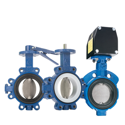
Generally speaking, electric actuators are divided into two categories: electric door and electric actuator baffle, electric actuators installed on steam, water, oil and other pipelines and valves (gate valves, ball valves, throttle valves) connected to the collectively referred to as electric door; electric actuators installed in the air ducts, flue ducts, above the collectively referred to as electric actuator baffle.
Electric actuators are designed to reduce labor, easy to operate, according to the control mode is divided into remote control and local control, electric actuators are widely used in electric power, petroleum, chemical industry, paper, water mills and other industries.

2. Working Principle
Electric actuators can be divided into integrated electric actuators and split electric actuators through the control circuit.
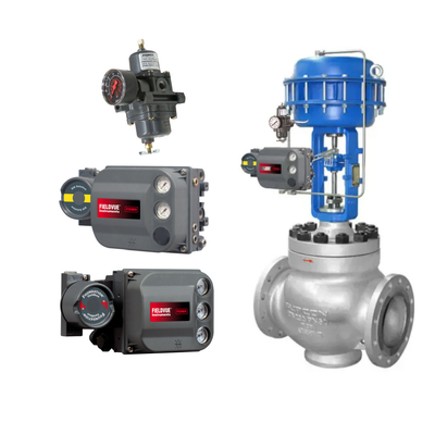
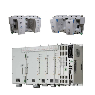
Integrated electric actuator: Electric actuator with control circuit integrated inside the actuator. Integrated electric actuator has motor, reducer, control mechanism, stroke controller, torque controller, push button assembly, hand-electric switching mechanism, handwheel part set and electrical parts.
Split electric actuator: electric actuator with separate control circuit and actuator. Split-type electric actuator has motor, reducer, stroke controller, torque controller, hand-electric switching mechanism, handwheel set, and on-site control box.
3. Structure Composition
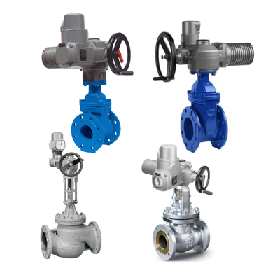
The electric actuator is driven by a three-phase servomotor, decelerated by a worm gear and driven by a hollow output shaft to rotate and output torque. In the speed box, there is a manual/automatic switching mechanism. When the switching handle is in the manual position, the handwheel is operated and the hollow output shaft is rotated by the clutch.
When the actuator is operated electrically, the manual/automatic switching mechanism automatically returns to the electric state, the clutch engages with the worm gear, and the three-phase motor drives the hollow output shaft. At the same time, a mechanical two-position travel switch and a torque switch are installed on the motor-driven worm shaft.
The stroke control mechanism adopts the principle of decimal counter with high control accuracy. The working principle is that a pair of large and small bevel gears in the reduction gearbox drive the active pinion, and then drive the counter work. If the counter according to the valve open, close position has been adjusted, when the counter with the output shaft rotates to the pre-adjusted position, then the cam will rotate 90º, forcing the microswitch action, cut off the power supply to the motor, so that the motor stops rotating, so as to realize the control of the motorized device trip. If the valve jams, the torque on the output shaft increases to a certain value, the worm gear in addition to the rotation will also produce displacement to drive the curvature of the angular displacement until the torque microswitch action, cut off the power supply, so that the motor stops rotating, thus realizing the control of the output torque of the electric device.
4. Commissioning of electric actuators
Integration, split electric actuator can also be divided into mechanical and intelligent type according to the type of commissioning, the so-called mechanical type is to manually adjust the travel gear to achieve the valve switch limit. Intelligent type is the internal intelligent controller and valve position sensor position signal comparison, the output shaft of the actuator is located in the position corresponding to the input signal, complete positioning. It can be realized by remote control or local control button.
Below we adjust the mechanical electric actuator to the German AUMA electric door and Yangzhou Siemens electric door as an example, as follows:
AUMA electric door commissioning method
Hand crank the stopper to the fully closed position (there should be a machine operator to confirm whether the stopper is fully closed or not).
Use a screwdriver to press the adjusting screw A shown in Figure 1 below, turn the adjusting screw A in the direction of the arrow, you can see that after turning the adjusting screw A for a certain period of time, B shown in Figure 1 above will turn 90 degrees, continue to turn the adjusting screw A until the pointer B turns to the position C, the shutdown feedback indicator will light up, stop turning the adjusting screw A. After releasing the screwdriver, the adjusting screw A will be slightly upward to return to the original position.
Note that when pointer B is only at the last 90 degree angle from position C, adjust adjusting adjusting screw A with the screwdriver should be slowed down, if pointer B has already reached position C and adjusting screw A is still turning, there may be a phenomenon of travel over-adjustment. So be sure to slowly turn the adjusting screw A at the last 90 degrees so that the pointer B reaches position C. Close the stroke to confirm the end.
Use a screwdriver to press the adjusting screw D shown in Figure 1 below, turn the adjusting screw D in the direction of the arrow, you can see that after turning the adjusting screw D for a period of time, E shown in Figure 1 above will turn 90 degrees, continue to turn the adjusting screw D until the pointer E turns to the position F, the on indicator light will be on, stop turning the adjusting screw F, after releasing the screwdriver, the adjusting screw D will be slightly upward to spring, restored to the original position, the on travel to confirm the End.
Auma Electric Valve Actuator

 Your message must be between 20-3,000 characters!