Introduction
When a control valve loses its control signal, instrument air, or electrical power, what should it do? The answer depends on the process and the consequences of losing control.
A valve may need to open to maintain cooling flow, close to isolate a hazardous feed, or remain near its last position to minimize process disturbance. These behaviors are commonly described as fail-open, fail-closed, and fail-in-place.
Selecting the right failure action is an engineering decision tied to the process safety requirements, not simply a preference for one actuator type.
1. What Does Fail-Open Mean?
A fail-open control valve is designed to move toward the open position following a defined failure condition.
This action may be appropriate when maintaining flow is necessary to reduce risk. For example, a cooling-water valve may be designed to open on loss of its control utility if continued cooling is the required safe response.
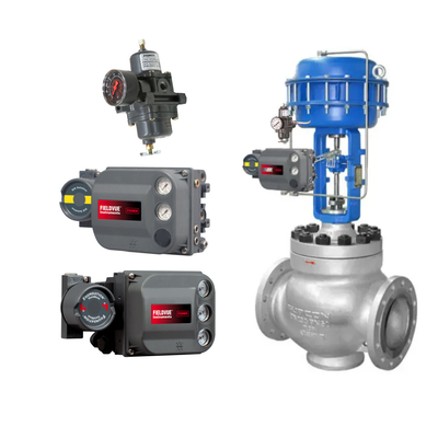
A common arrangement uses a pneumatic actuator with a spring-return mechanism. During normal operation, air pressure moves the actuator against the spring. When the relevant air supply is lost, the spring drives the valve toward its designated failure position.
However, fail-open behavior should never be assumed from the actuator alone. Valve orientation, actuator configuration, accessories, and the specified failure scenario must all be verified.
2. What Does Fail-Closed Mean?
A fail-closed valve moves toward the closed position under its specified failure condition.
This may be required to isolate fuel, chemical feed, or another process stream when continued flow could create a hazardous situation.
Spring-return actuators can provide this function when configured to close the valve as air pressure is lost. A suitable solenoid valve or other control accessory may be used where required by the system design.
The important point is that fail-closed does not mean every valve in a process should close when something goes wrong. Closing a valve can itself create risk, such as interrupting essential cooling or trapping pressure. The safe action must be established through process hazard analysis and the applicable safety requirements.
3. What Does Fail-in-Place Mean?
Fail-in-place generally describes an arrangement intended to maintain the valve near its existing position after a specified failure, rather than deliberately driving it fully open or closed.
This can help reduce abrupt process changes when a sudden movement would be undesirable. However, maintaining position after loss of air or power requires an arrangement capable of retaining the required actuator force or position.
A double-acting pneumatic actuator alone does not guarantee fail-in-place behavior. If both sides of the actuator lose their effective pressure, the valve may move due to process forces, friction, leakage, or other external influences.
A lock-up valve, suitable pneumatic accessories, or a dedicated position-holding arrangement may be used in some designs. The actual behavior depends on how the complete assembly responds to the particular failure.
Fail-in-place should not automatically be treated as the safest option. If the valve position is unsuitable for the process after a failure, holding it there may prolong the hazard.

4. How Actuator Type Affects Failure Action
The actuator is a major part of the failure-action design.
Spring-return pneumatic actuators use a spring to move the valve toward a predetermined position when the relevant air pressure is lost. They are commonly used where a defined fail-open or fail-closed response is required.
Double-acting pneumatic actuators use air pressure to drive movement in both directions. They can provide substantial operating force, but a defined failure response requires additional consideration of how air pressure is maintained, released, or redirected.
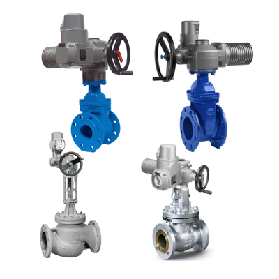
Electric actuators may have different responses depending on their power-loss behavior, stored energy, backup power, and actuator configuration. Some systems can move to a predetermined position, while others may stop where they are. The specific design must be verified.
For any actuator type, the required torque or thrust, process forces, travel, and valve operating conditions must be considered together.
5. What About Lock-Up Valves and Other Accessories?
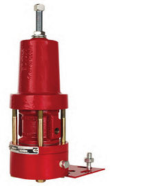
Pneumatic lock-up valves are used in certain systems to retain actuator-side air pressure when the supply pressure falls below a defined level. They can help prevent unintended valve movement during an air-supply failure.
Examples of related products include the Fisher 377 trip valve and lock-up solutions from SMC or other pneumatic control suppliers. These products serve different functions and should not be assumed to be interchangeable.
A lock-up valve does not automatically make a control valve fail-in-place under every failure condition. Leakage, actuator integrity, valve forces, tubing arrangement, and the particular accessory configuration all affect the result.
If electrical power loss is also part of the design scenario, the response of the positioner, solenoid valve, and other electrical accessories must be evaluated separately.
6. How to Choose the Appropriate Failure Action
Before specifying a control valve, answer these questions:
-
What happens if the valve remains open during a failure?
-
What happens if the valve closes suddenly?
-
Is continued cooling, ventilation, or minimum flow required?
-
Could the process medium create a fire, toxic release, overpressure, or environmental hazard?
-
Which utility failure must the valve respond to: instrument air, electrical power, control signal, or more than one?
-
Is a defined movement required, or is maintaining the existing position acceptable?
-
How will the valve's actual failure action be tested and verified?
The answers should be documented in the control valve specification and coordinated with the process control and safety system design.
7. Common Mistakes to Avoid
One common mistake is assuming that a 4–20 mA signal failure and an instrument-air failure produce the same result. They may trigger different actions depending on the configuration.
Another is selecting a spring-return actuator without checking whether its available output is sufficient under the actual process conditions.
It is also important not to rely on the positioner setting alone. A command that requests a particular valve position is not necessarily the same as a mechanically guaranteed response after all utilities are lost.
Finally, the specified failure action should be confirmed during commissioning using an approved test procedure and appropriate process safeguards.
Conclusion
Fail-open, fail-closed, and fail-in-place arrangements serve different process needs. The right choice depends on the consequences of continued flow, interrupted flow, or sudden valve movement under the specified failure conditions.
Spring-return actuators, double-acting actuators, positioners, and lock-up accessories can all play a role, but the complete assembly must be evaluated as a system.
For project procurement, clearly specifying the required failure action and the exact failure scenario helps prevent mismatched actuator packages and unexpected behavior during commissioning.


 Your message must be between 20-3,000 characters!