1, Design and Operating Principle
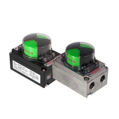
1.1 Introduction to the Logix 3200MD Positioner
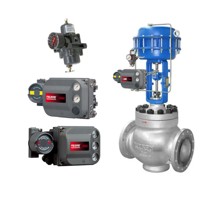
The Logix 3200MD digital positioner is a two-wire, 4-20 mA input digital valve positioner that can be configured through the local user interface. The positioner can be configured through the local user interface.The Logix 3200MD utilizes the HART protocol, which allows for bi-directional remote communication through the positioner.The Logix 3200MD positioner can be mounted on straight or rotary stroke double acting and single acting actuators. The positioner is driven exclusively by a 4-20 mA input signal. Start-up current must be at least 3.6 mA (without analog output card) or 3.85 mA (with analog output card).

1.2 Positioner operating principle
Assume that the device is configured as follows: the device is an analog command source; the valve deviation is zero, the current output signal is 12 mA; the loop is calibrated: 4 mA = 0% command, 20 mA = 100% command; the actuator is of the cylinder type and the positioner is of the air-open type.
Under the above conditions, 12 mA represents 50% of the command source. User-defined customization is disabled, so command sources become control commands 1:1. Since there is no deviation, the stem position is also at the 50% position. When the stem reaches a predetermined position, the slide valve is in an intermediate position that balances the up and down pressures on the piston in the actuator. This is often referred to as the zero or balanced spool position. Suppose the input signal changes from 12 mA to 16 mA. The positioner accordingly appears to be 75% of the commanded source. For a linear characteristic curve, the control command becomes 75%. Indicates the deviation between the control command and the spool position: Deviation = 75% - 50% = +25%, where 50% indicates the current spool position. With this positive deviation, the control algorithm sends a signal to move the slide valve spool upwards from its current position. The upward movement of the slide valve spool supplies air to the bottom of the actuator and discharges the air from the top of the actuator. This new differential pressure causes the valve stem to start moving 75% of its intended position. As the stem moves, the deviation begins to decrease. The control algorithm begins to reduce the spool opening of the slide valve. This process will continue until the deviation becomes zero. At this point, the spool will return to zero or equilibrium. The spool will stop moving and reach a predetermined position. Now let's discuss one more important parameter: the inner loop offset. As shown in Figure 2, the output of the control algorithm adds a number called the inner loop offset. In order for the slide valve spool to maintain a zero or equilibrium position, the control algorithm must output a non-zero slide valve spool command. This is the purpose of the inner loop offset. The value of this number is the same as the signal that must be sent to the slide valve spool position controller to bring it to zero position without deviation. This parameter is important for proper control and is automatically optimized and set during the stroke calibration process.
2, Calibration method and procedure
1, QUICK-CAL button and ↑ and ↓ three buttons at the same time, press and hold three wonderful clock, the diode state yellow-green-red-red, at this time, release the three buttons, you can use ↑ and ↓ for valve switching operations. Press the QUICK-CAL button to exit the manual operation and restore the automatic state.
2, first of all, will be adjusting DIP switch to Jog position, the user can only manually set the full range, can not be set to fully closed position, the valve fully closed position for the default state. When the DIP switch is set to Jog position, the status of the diode of the positioner is yellow-red-red-green. At this time, the user then use the Jog button ↑ ↓ manually adjust the valve to the desired 100%, after the valve is in place, press the ↑ and ↓ buttons at the same time, the valve is automatically adjusted, and so the diode after the end of the adjustment of the state of the diode to return to the yellow-red-red-green, and then re-set to 100% of the setting is complete, the setting is complete. After the setting is completed, press the ↑ and ↓ buttons at the same time, the valve is automatically adjusted. After the adjustment is completed, the status of the diode starts in green. This indicates that manual commissioning is complete and the positioner is normal.
WARNING: During a quick-calibration operation, the valve may actuate suddenly. Inform the relevant personnel of the possible operation of the valve to avoid injury and ensure that the valve is completely isolated.
3, List of internal parameters of the positioner
- GGGG
- Normal operation-analog command mode
- GGGY
- Tight shutoff(MPC) active
- GGYG
- Digital command mode
- GGYR
- Initializing
- GGRG
- Cycle limit exceeded (user set)
- GGRY
- Travel limit exceeded (user set)
- GYYR
- Lower soft stop reached (user set)
- GYRY
- Upper soft stop reached (user set)
- GYRR
- Squawk mode (user set )
- GRGR
- Piezo control voltage low
- GRYR
- Lower position alert (user set)
- GRRY
- Upper position alert (user set)
- YGYG
- signature test in progerss
- YGRR
- local jog command mode
- YYGR
- perssure calibration in progress
- YYYG
- loop calibration in progerss
- YYYY
- local user interface disabled
- YRGG
- stroke calibration in progress
- YRGR
- feedback unstable while calibration
- YRYG
- setting IL offset while calibration
- YRYY
- no feedback motion while calibration
- YRYR
- feedback 0% out of range
- YRRG
- waiting-adjust to full open position
- YRRY
- feedback 100% out of range
- YRRR
- feedback span too small
- RGYY
- pressure reading out of range
- RGYR
- loss of supply pressure
- RGRR
- position deviation alert (user set )
- RYGG
- factory reset condition-recalibration
- RYYY
- pneumatic relay position alert
- RRGG
- watch dog timer timeout
- RRYG
- internal temperature alert
- RRYY
- piezo valtage error
- RRYR
- shunt volatge reference
- RRRY
- nv ram checksum error
- RRRR
- position deyiation alarm
4, the relevant gas source control components failure emergency treatment.
- 1,Leakage of air source gas line joints
A: Replace the gasket or clamp re-tightening, if necessary, in the joints wrapped raw material tape.
- 2,Gas source pressure gauge is damaged
A: Replacement of the appropriate pressure gauge, the pressure gauge joints wrapped in raw material tape to prevent air leakage of gas source joints.
- 3,Gas source filter pressure reducer is not gas, leakage or damage
Filter pressure reducer for sewage, observe whether it is clogged or no air source; tighten the leakage; if the filter pressure reducer can not be repaired damage to replace the new spare parts.
- 4,Positioner problems can be directly replaced with a positioner or with a backup gasifier corresponding to the valve for reciprocal use.

 Your message must be between 20-3,000 characters!