I. Introduction
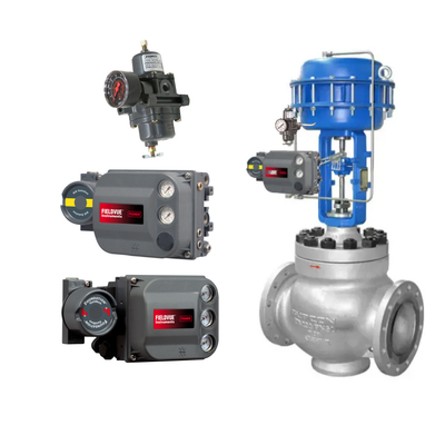
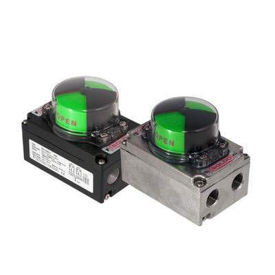
Logix510Si intelligent positioner accepts 4-20mA analog input and can 4-20mA analog output.
II. Flowserve positioner operating panel introduction
Logix510Si intelligent positioner local operation panel consists of QUICK-CAL quick adjustment buttons that can automatically adjust the zero point and full scale, and two push buttons (↑ and ↓) that can manually operate the positioner, as well as eight DIP switches and rotary switches that can adjust the gain of the positioner.
III. Setting the Positioner DIP Switches
Before the positioner is operated, the DIP switches are first set. The following describes the settings for each DIP switch.
-
Mode of action
There are two types of actuating modes, ATO and ATC, which are set according to the type of valve before commissioning.
-
Valve closing signal
4mA Signal 4mA when the valve is in the fully closed position, 20mA when the valve is in the fully open position.
20mA Signal 20mA when the valve is in fully closed position, signal 4mA when the valve is in fully open position.
-
Valve position and signal corresponding curve
Linear curve (Linear) Valve position and signal into a linear relationship
Selection curve (% =) valve position and signal into equal percentage
-
Small signal cutting function
On When the signal is less than 1%, the valve is fully closed
Off small signal cut off function is lifted
-
Automatic calibration
on Each time the QUICK-CAL button is pressed, the positioner automatically calculates the gain for commissioning.
off Forces the positioner to use the factory pre-setting, i.e., the position of the rotary switch that adjusts the positioner gain, for commissioning.
In either case, the rotary switch for adjusting the gain of the positioner can be adjusted, and the adjustment is instantaneous without re-commissioning.
-
Positioner debugging mode
Auto Positioner automatic debugging
Jog manual commissioning, the user can manually determine the position of the valve 100% according to need.
-
Stability switch
Low-Friction Valves For low-friction valves.
High-Friction Valves For high friction valves.
-
Input and output settings
Input Calibration command signal
Output Calibration output signal

IV. Manual commissioning
First of all, the tuning DIP switch will be dialed to the Jog position, the user can only manually set the full range, can not be set to the full closed position, the valve full closed position is the default state. When the DIP switch is set to Jog position, the status of the diode of the positioner is yellow-red-red-green. At this time, the user then use the Jog button ↑ ↓ to manually adjust the valve to the desired 100%, after the valve in place, press the ↑ and ↓ buttons at the same time, the valve is automatically adjusted, so that the end of the adjustment diode state back to yellow-red-red-green, and then re-perform the 100% setting, setting is complete, press the ↑ and ↓ buttons at the same time. After the setting is completed, press the ↑ and ↓ buttons at the same time, the valve is automatically adjusted. After the adjustment is completed, the status of the diode starts in green. This indicates that the manual commissioning is completed and the positioner is normal.
V. Local manual operation
QUICK-CAL button and ↑ and ↓ three buttons at the same time press and hold three wonderful clock, the diode state yellow-green-red-red, at this time release the three buttons, you can use ↑ and ↓ for valve switching operations. Press the QUICK-CAL button to exit the manual operation and restore the automatic state.
Press the QUICK-CAL button to exit manual operation and return to automatic state.
Supplementary: Logix500si Positioner Commissioning Instructions
-
Tight Shutoff Switch
ON means that the regulating valve is fully closed when the command signal is less than 1%.
OFF means the function is disabled.
-
Loop Calibration Commissioning Methods
There are two types of Loop Calibration: Input Loop Calibration (Input Command Loop Calibration) and Output Loop Calibration (Output Feedback Loop Calibration).
Input Loop Calibration (Input command loop commissioning) and Output Loop Calibration (Output feedback loop commissioning)
Input Loop Calibration method:
Before debugging, you need a signal generator, connect the signal generator to the terminals 11 and 12 of the positioner, and set the DIP switch to the Input position, then the LED status is yellow-green-green-yellow, and the flashing sequence indicates that the signal generator needs to input the *smallest* command signal, if it is a 4-20mA standard signal, 4mA is the *smallest* command signal, if it is a segmented control, it needs to input the required *smallest* command signal. If it is segmented control, it needs to input the required * small command signal, after the signal generator gives the signal, press the ↑↓ two buttons at the same time; the status of the LED becomes yellow-green-yellow-red, which indicates that the input setting of the small signal is completed, and wait for the signal generator to input the * big command signal, which should be 20mA normally, if it is segmented control, it needs to input the command signal within the command range * big command signal, after the signal generator gives the signal, press the ↑↓ two buttons at the same time, this blinking sequence indicates that it needs the signal generator to input the * small command signal. When the signal is given by the signal generator, press the ↑↓ two buttons at the same time, then the status of the LED becomes yellow-yellow-green-green, which indicates that the debugging of the input signal has been completed. At this time, the command signal will be adjusted to the required position, and press the ↑↓ two buttons at the same time, is the positioner back to the normal operation of the state.
Note: The command signal debugging is only related to the milliampere value corresponding to 0% and 100% of the signal, but it does not affect the position debugging of the positioner, and it is necessary to re-tune the positioner debugging.
VI. Logix500si Fuchs valve positioner operating principle
Logix500Si series positioner is a digital intelligent positioner that can meet different needs. It is divided into three parts:
- control module with microprocessor including operation panel
- electrical switching module with piezoelectric valves
- valve position sensor

 Your message must be between 20-3,000 characters!