How do control valves work?
Introduction: The key role of control valves in industrial automation
Definition of a control valve: More than just on/off
Control valves are indispensable power-operated devices in the field of industrial automation, with their core function being the precise regulation or manipulation of fluid flow (such as gas, oil, water, and steam) within pipelines and process equipment. Unlike simple on/off valves, control valves can perform precise throttling control to achieve the desired flow rate. In automatic control terminology, control valves are typically referred to as “final control elements."
The term “final control element" is not merely a coincidental naming convention; it reveals the unique position of control valves within the entire control loop. Controllers (such as programmable logic controllers (PLCs) or distributed control systems (DCSs)) determine the actions to be executed (e.g., “increase flow by 10%"), while control valves are the only physical components capable of actually executing such commands, thereby directly influencing process variables (such as fluid flow, pressure, temperature, and level). They serve as the bridge between abstract control logic and the physical process world. Therefore, the reliability, accuracy, and response speed of control valves directly determine the overall performance, stability, and efficiency of the entire control system, thereby impacting the quality and safety of the final product or process. A perfectly tuned controller would have minimal effect without a “well-performing" final control element. This underscores the foundational importance of understanding how control valves work, as they are the cornerstone of successful industrial automation.
Why control valves are indispensable: regulating process variables
Control valves are critical for maintaining the required process conditions, achieving this by directly controlling parameters such as flow, pressure, temperature, and level. Their ability to regulate fluid flow ensures efficiency, safety, and optimal performance across various industrial sectors. Even in the face of load disturbances, control valves actively respond to changes in process variables to maintain the setpoint.
Overview of Key Components
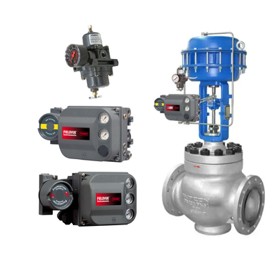
An automatic control valve assembly typically consists of three main parts: the valve body, the valve actuator, and the valve positioner, which is usually included. These components work together to convert control signals into precise physical adjustments of fluid flow.

Control Valve Structure: Core Components and Their Functions
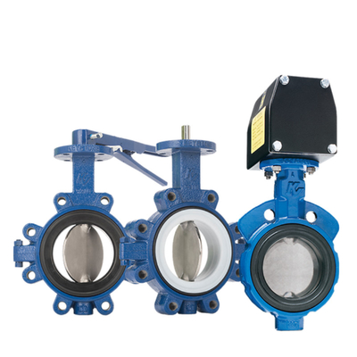
Valve Body and Internal Components: Guiding and Regulating Flow
The valve body is the pressure-bearing component of the valve, featuring inlet and outlet ports and internal orifices or openings through which the controlled fluid flows. It defines the fluid path and must be capable of withstanding the pressure and temperature of the process fluid.
Valve internals are the internal components that directly interact with the fluid to regulate its flow. They typically consist of a valve plug (or valve disc), valve seat, and valve stem. The movement of the valve plug relative to the valve seat alters the size of the fluid passage, thereby controlling the flow. Different valve internals designs (e.g., V-port, segmented ball) can provide specific flow characteristics to achieve precise control.
Valve actuators: the “muscle" of control valves
Purpose: An actuator is a mechanism that converts control signals (electrical, pneumatic, or hydraulic) into mechanical motion to open, close, or regulate the valve's control element. This enables valves to be operated remotely and automatically, particularly in situations where manual operation is impractical or unsafe, such as in large, remote, or hazardous environments.
Actuator Types and Their Operating Principles
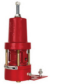
- Pneumatic Actuators: These actuators utilize compressed air or gas as a power source.
- Operating Principle: Air pressure is applied to a diaphragm or piston, generating force that causes the valve stem to move linearly (diaphragm, piston actuators) or rotate the shaft (gear rack, fork-type actuators).
- Configuration: They can be classified as single-acting (air moves in one direction, spring-return) or double-acting (air moves in both directions).
- Hydraulic Actuators: Similar to pneumatic actuators, but they convert pressurized fluid (typically oil or water) into motion.
- Working principle: Fluid pressure acts on the piston, generating high force and torque, suitable for heavy-duty applications.
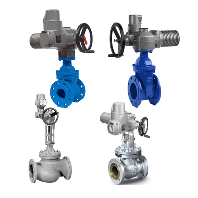
- Electric actuators: These actuators use an electric motor to generate the motion required to operate the valve.
- Working principle: The rotation of the electric motor is converted into linear or rotational motion via gears or a lead screw to drive the valve stem.
- Forms: Multi-turn actuators for linear valves (gate valves, globe valves) and quarter-turn actuators for rotary valves (ball valves, butterfly valves).
- Electro-hydraulic actuators: These actuators combine an electric motor with a hydraulic power unit, leveraging the high force of a hydraulic system with the precise control advantages of an electric actuator.
AUMA Electric Valve Actuator
Comparative analysis: Advantages, disadvantages, and typical applications
The selection of actuators is not solely based on performance but involves a complex trade-off between environmental conditions (hazardous vs. non-hazardous), safety regulations, available infrastructure (compressed air vs. electricity), required force/torque, speed, precision, and overall cost (initial cost vs. operational/maintenance costs). For example, in refineries, the inherent safety of pneumatic actuators (spark-free) may outweigh the precision or remote control advantages of electric actuators, or explosion-proof electric designs may be required. Conversely, in a pharmaceutical plant, the cleanliness and precision of electric actuators may be prioritized. This highlights that the selection of control valves is a critical engineering decision directly impacting process safety, operational efficiency, and long-term ownership costs. It requires a holistic perspective beyond technical specifications, incorporating risk assessment, regulatory compliance, and economic feasibility. Improper application may lead to “catastrophic failure," underscoring the significant risks involved.
The table below provides a detailed comparison of different types of valve actuators:
| Type |
Power Source |
Motion Direction |
Advantages |
Disadvantages |
Typical Applications |
| Pneumatic |
Compressed Air/Gas |
Linear/Rotary |
Fast operating speed, cost-effective, intrinsically safe (no electricity required, minimizes sparks), can operate during power outages, simple design |
Limited strength/power (not suitable for heavy loads), shorter lifespan than hydraulic systems, susceptible to water/extreme temperatures, requires compressed air supply and maintenance |
Process control, chemical industry, food and beverage, hazardous environments |
| Hydraulic |
Pressurized fluid (oil/water) |
Linear/rotary |
High force/torque output, high precision control, high energy efficiency, suitable for heavy-duty/large valves, fast cycle time |
Higher initial cost, more complex installation and system design, requires a hydraulic pump system, prone to fluid leakage, high maintenance requirements |
Natural gas pipelines, power plants, oil and gas industry, hydroelectric power stations, industrial machinery |
| Electric |
Electric power (motor) |
Linear/rotary |
Precise control, programmable, clean (no emissions/leaks), quiet operation, easy integration with automation systems, high torque, stable speed, remote control capability |
Susceptible to power outages, typically heavier, higher cost (especially for larger models), may be complex, not suitable for hazardous/explosive environments unless specially designed |
Power generation, water treatment, pharmaceutical industry, applications requiring precise control and automation, IoT integration |
Fail-safe mechanism: Ensuring operational safety
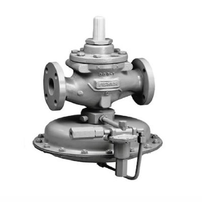
Control valves are typically designed with a fail-safe mode (fail-open, fail-close, or fail-to-last-position) to ensure that they enter a predetermined safe state in the event of power or control signal loss. This is typically achieved through internal springs, which provide restoring force to move the valve to its default position when pneumatic or electric actuation force is lost. For example, single-acting pneumatic actuators use spring-return mechanisms.
Valve Positioners: The “Brain" for Precise Control
Purpose: Positioners are critical motion control devices that significantly enhance the precision, speed, and stability of control valves. They act as an intermediary between the control system and the valve actuator.
Enhancing Precision and Overcoming Interference
Positioners are essential for overcoming issues such as packing friction, actuator lag, and unbalanced forces on the valve plug, which could otherwise lead to inaccurate valve positioning. By continuously comparing the desired position with the actual valve position and making adjustments, they ensure the valve precisely reaches and maintains the commanded opening.
If the actuator simply converts the signal into force, why is a positioner necessary? Data shows that, for many industrial applications, the actuator alone is insufficient in terms of precision. Factors such as valve stem packing friction, internal force imbalance, and actuator lag introduce nonlinearity and inaccuracies. The positioner's role is not merely to “amplify" the signal but to create a local feedback loop that actively “counteracts" these mechanical defects. It continuously measures the valve's actual position and adjusts the actuator's output until it matches the desired position, regardless of external disturbances. This design reveals a fundamental design principle in control systems: hierarchical control to address specific challenges. The main process controller handles overall process variables (e.g., temperature), while the positioner handles the sub-control of the valve's physical position. This “cascade control" achieves powerful high-precision control, which is impossible to achieve in a simpler direct actuator-to-controller connection. It emphasizes that industrial control often involves complex nested loops to achieve the desired performance.
Faster response times
Positioners improve the response time of control valves to changes in process variables, enabling faster loading and venting and minimizing the time spent operating outside the set point. They can also act as boosters, supplying and exhausting high-flow air to actuators.
Types of Positioners and Their Operating Principles
- Pneumatic Positioners: This is the oldest and most widely used type, receiving and transmitting pneumatic signals.
- Operating Principle (Force Balance): They operate based on the principle of force balance. Pneumatic control signals (e.g., 3-15 psi) apply pressure to the diaphragm. This force is balanced by the feedback force from the actual position of the valve stem (via the cam and range spring). Any imbalance causes the diaphragm-nozzle system to supply or exhaust air to the actuator until a new balance is achieved, thereby precisely positioning the valve stem.
- Electro-Pneumatic (EP) Positioners: These hybrid devices convert electrical control signals (typically 4-20 mA or 0-10 VDC) into pneumatic output signals to control the valve actuator.
- Working principle: They contain a current-to-pressure (I/P) converter that converts the electrical input into a proportional pneumatic signal, and their operation is similar to the force-balancing mechanism of pneumatic positioners.
- Digital/smart positioners: These represent the most advanced type, utilizing microprocessors and digital technology to control valve actuators.
- Working Principle: The microprocessor reads digital or analog electrical control signals (e.g., 4-20 mA, HART, Foundation Fieldbus, Profibus), processes them using digital algorithms, and converts them into the drive current for the I/P converter. The resulting pneumatic pressure is routed to the pneumatic amplifier, which then adjusts the actuator. Valve position feedback is continuously fed back to the microprocessor for precise control.
Fisher DVC6200SIS Valve Positioner
Comparative Analysis: Advantages, Disadvantages, and Application Suitability
The evolution of positioners from pneumatic to electric, and then to digital/smart positioners, clearly reflects the broader trend in industrial automation toward digitalization, data-driven decision-making, and predictive maintenance. Pneumatic positioners are renowned for their ruggedness and intrinsic safety. Electromechanical positioners introduced electrical signal compatibility and higher precision. However, digital positioners represent a paradigm shift: they integrate microprocessors, enabling advanced diagnostic functions, self-calibration, and digital communication protocols (HART, Fieldbus, Profibus). This direction signifies a shift in maintenance strategies from purely passive or time-based maintenance toward condition-based and predictive maintenance. Smart positioners act as data nodes, providing real-time information about valve health and performance, thereby optimizing uptime, reducing operational costs, and enhancing overall plant efficiency. This directly embodies the principles of Industry 4.0 at the component level, highlighting the growing integration of IT and OT (operational technology).
The following table compares different types of valve positioners:
| Type |
Input Signal |
Operating Principle |
Accuracy/Resolution |
Complexity |
Cost |
Key Features/Advantages |
Disadvantages |
| Pneumatic |
(e.g., 3-15 psi, 0.2-1.0 bar) |
Force balance (flap-nozzle) |
Limited |
Simple |
Low |
Reliable, robust, intrinsically safe (no electricity required, minimizes sparks), suitable for hazardous environments |
Limited accuracy/resolution, limited versatility, requires clean air supply |
| Electropneumatic |
Electrical (e.g., 4-20 mA, 0-10 VDC) |
Converts electrical signals to pneumatic signals (I/P converter), then performs force balancing |
Higher than pneumatic |
More complex |
Higher than pneumatic |
Combines the precision of electronic control with the robustness of pneumatic systems, capable of processing electrical signals, faster response time, can act as a booster |
More complex design, higher cost, requires electrical and pneumatic infrastructure |
| Digital/smart |
Electrical (e.g., 4-20 mA, HART, Fieldbus, Profibus) |
Microprocessor-based control, digital algorithms, I/P conversion |
High |
Most complex |
Highest |
Advanced diagnostics (e.g., force balancing, stick-slip, air path), self-calibration, remote monitoring, digital communication capabilities, predictive maintenance, lower air consumption |
Highest initial cost, full utilization requires expertise |
The Importance of Calibration and Diagnostics
Proper installation and calibration (zero and span adjustment) are critical to ensuring that positioners operate accurately and efficiently. Digital positioners offer advanced diagnostic capabilities that can detect valve abnormalities, signs of deterioration (e.g., packing seal deterioration, air supply issues), and internal positioner problems during operation. This enables maintenance to shift from time-based to condition-based, thereby reducing costs and downtime.
Control Loop: How Control Valves Integrate and Respond
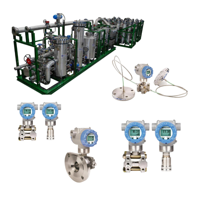
Control System Signals: Translating Desired Outcomes
Control valves receive signals from process control systems (such as PLCs or DCSs) that represent the desired setpoints for process variables. Common industrial control signals include pneumatic signals (traditionally 3-15 psi or 0.2-1.0 bar) and electrical signals (most commonly 4-20 mA DC or 0-10 VDC). For electrical signals, an I/P (current-to-pressure) converter is typically used to convert the electrical signal into a pneumatic signal for use by pneumatic actuators/positioners. Some positioners have built-in I/P converters (i.e., electro-pneumatic positioners).
The choice of a current loop (4-20 mA) over a voltage signal (such as 0-10 V) is a well-considered engineering decision based on real-world industrial environments. Current signals exhibit greater resistance to long-distance cable transmission and electromagnetic interference (noise), which are common challenges in large industrial plants. Its “live zero point" (4 mA represents 0% output rather than 0 mA) is a clever design feature for fault detection: if the wire breaks or power is lost, the signal drops to 0 mA, immediately indicating a fault, whereas in a voltage signal, 0 V could indicate either 0% output or a fault. This standardization and design choice significantly enhances the reliability and maintainability of industrial control systems. It simplifies troubleshooting, reduces downtime by quickly identifying communication faults, and ensures robust signal transmission in electrically noisy environments. This seemingly minor technical detail has a profound impact on the operational integrity of the entire plant.
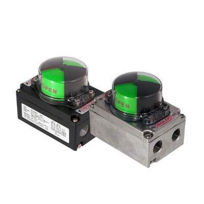
Feedback Mechanism: Ensuring Precise Valve Positioning
A critical aspect of control valve operation, especially when using a positioner, is the feedback mechanism. The positioner continuously measures the actual position of the valve stem or actuator via a potentiometer, position sensor, or mechanical linkage (cam and lever system).
The actual position is compared with the desired position (derived from the control signal). Any deviation (error signal) triggers the positioner to adjust the pneumatic or electrical output applied to the actuator until the valve reaches the commanded position. This forms a closed-loop control system within the valve assembly.
This configuration describes a cascaded control system. The master controller manages the overall process variable (e.g., tank level) and sends the setpoint to the secondary controller (positioner). The positioner's role is to ensure the valve's physical position accurately tracks its setpoint, compensating for local disturbances (friction, pressure changes) that the master controller may not effectively handle or even directly “see." This design decouples the valve's mechanical behavior from overall process control, making the system more robust and easier to tune. This hierarchical approach significantly improves process stability and accuracy. Without a positioner, the master controller would have to directly handle the valve's nonlinearity and disturbances, leading to oscillations, slower response times, and poor control performance. The cascade structure allows for faster responses to changes and better suppression of disturbances, ultimately improving product quality and process efficiency.
Flow Regulation: Achieving Proportional Control
Control valves are designed for proportional control, meaning they can be set to any position between fully open and fully closed, allowing partial flow through. The valve opening is proportional to the received control signal. For example, a 4mA signal may fully close the valve, a 20mA signal fully open it, and a 12mA signal position it at 50% opening. This proportional control is critical for maintaining precise process variables (such as temperature or pressure) by continuously adjusting flow.
Understanding Control Actions: Pneumatic/Electric Open and Pneumatic/Electric Close
Control valves can be configured with different control actions based on safety requirements and process needs:
- “Pneumatic/Electric Open" (fail-closed): As the control signal value increases, the flow restriction decreases (valve opens). If the signal fails, the valve closes.
- “Pneumatic/Electric Close" (Fail-Open): As the control signal value increases, the flow restriction increases (the valve closes). If the signal fails, the valve opens.
The selection of the fail-safe mode is critical for process safety, ensuring that the system defaults to a safe state in the event of power or signal loss.
Industrial Applications: Areas Where Control Valves Play a Role
Cross-Industry Impact
Control valves are ubiquitous in modern industrial environments, playing a key role in precisely controlling fluid flow across a wide range of applications.
Specific examples of control valve deployment
- Oil and gas industry: Used in pipelines, offshore platforms, refineries, and wellhead control systems to regulate the flow of crude oil, natural gas, and other fluids. They manage complex processes such as throttling control, pressure regulation, and emergency shutdown, typically operating under extreme pressure and corrosive conditions. Pneumatic positioners are particularly favored for their intrinsic safety in explosive environments.
- Water treatment plants: Critical for regulating water levels, chemical dosing, and pressure during water treatment processes. They ensure optimal treatment processes and prevent waste or contamination.
- Chemical processing: Critical for precisely controlling the flow of volatile chemicals, maintaining process stability, and ensuring safety in potentially hazardous environments.
- Power generation: Used to control steam flow, cooling water, fuel supply, and other critical parameters in power plants, helping to improve efficiency and safety.
- Pharmaceutical Production: Ensures accurate and repeatable control of fluid flow in applications ranging from ingredient mixing to reaction condition control and product filling.
- Mining and Nuclear Industry: Applied in various harsh environments requiring precise flow and pressure regulation.
- Food Processing Plants: Used to control the flow of various liquids and ingredients.
The role of control valves goes beyond simple setpoint regulation. In specific industries, they also achieve:
- Safety: In the oil and gas industry, they are critical for emergency shutdowns and managing extreme pressures.
- Quality control: In the pharmaceutical and food industries, precise flow ensures consistent product quality.
- Resource efficiency: In water treatment, they prevent waste and ensure optimal chemical dosing. In the energy sector, they minimize energy consumption by precisely maintaining temperature setpoints.
- Environmental compliance: Electric actuators are increasingly popular due to their zero emissions, and pneumatic systems can also use steam recovery devices.
These examples demonstrate that control valves are not merely components; they are strategic assets that directly help companies achieve production goals, comply with stringent safety and environmental regulations, optimize resource utilization, and ultimately gain a competitive advantage. Their proper deployment and maintenance are directly linked to operational excellence and sustainable industrial practices.
Conclusion: Optimizing Process Control Through Control Valves
Basic Working Principle Review
Control valves are indispensable “final control elements" that precisely regulate fluid flow and related process variables (pressure, temperature, liquid level). Their operation relies on the coordinated action of the valve body and internal components, actuators (pneumatic, hydraulic, or electric), and typically equipped positioners. Actuators provide the mechanical force to move the valve, while positioners act as complex feedback controllers, ensuring the valve reaches and maintains the precise position specified by the control system while overcoming internal and external disturbances.
Strategic Selection and Maintenance for Optimal Performance
Selecting the appropriate control valve components (actuator type, positioner type) is critical based on application requirements, including accuracy, speed, safety, environmental conditions (e.g., hazardous areas), power availability, and cost considerations. Proper installation, regular calibration, and utilization of advanced diagnostic features (especially in digital positioners) are critical to ensuring the optimal performance, lifespan, and reliability of control valve systems.
The Evolution of Control Valve Technology: Toward Smarter, More Efficient Systems
The evolution from manual to pneumatic, then to electromechanical, and finally to digital/smart control valves and positioners reflects the ongoing pursuit of higher precision, greater automation, and enhanced data-driven insights in industrial processes. Modern “smart" positioners, with their diagnostic and communication capabilities, are transforming maintenance strategies from reactive to predictive, significantly improving plant efficiency, reducing downtime, and optimizing resource consumption. This evolution aligns with the broader trend of Industry 4.0, which emphasizes connectivity, data analysis, and smart automation to achieve a more stable, efficient, and safe industrial environment.

 Your message must be between 20-3,000 characters!