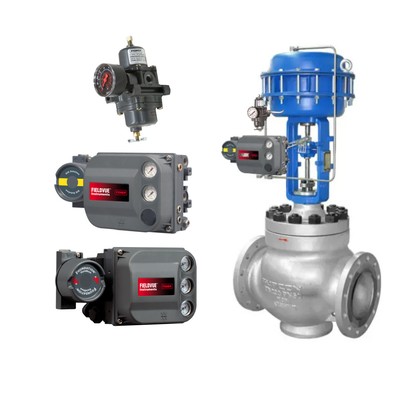
What is a Pneumatic Valve Positioner?
A pneumatic valve positioner is an instrument used to position the stem of a control valve based on a 3 to 15 PSI air pressure signal received from a controller or manual loading station.
The Pneumatic Valve Positioner is used to increase or decrease air pressure to actuate an actuator, which ensures reliable and accurate control valve operation.
How does a pneumatic valve positioner work?
Pneumatic valve positioners work on the principle of force balance.
In this force balance principle, the chamber has three ports for instrument air input, control signal output and exhaust.
The pressure on the lever arm is changed or regulated by a flexible diaphragm through an external sensor.
When the sensor presses down on the right end of the lever, the left end of the lever lifts upward, opening the air supply valve.
As a result, both the pressure in the chamber and the control signal on the output tube increase, causing movement of the controlled device.
As the air pressure in the chamber increases, the diaphragm is forced upward against the pressure of the sensor until the system is again in equilibrium at the higher pressure and the air supply valve closes.
What is the purpose of a pneumatic valve positioner?
The main role or purpose of a positioner in a control valve is to create an interface between the PLC and the actuator to accurately regulate the position of the spool to open and close the regulating valve.
A positioner used in a control valve for a specific circuit acts as a translator. It converts the PLC language into the corresponding actuator language.
This means that the positioner converts a given 4 to 20 mA DC current signal into a proportional air pressure signal of 3 to 15 PSI.
The operating principle of the pneumatic valve positioner is explained here.

The pneumatic positioner contains an internal I-P sensor.
Noun: I-P Sensor
I-P sensors are used in a wide range of industrial automation applications, especially where precise control of pneumatic actuators is required. The I-P sensors are widely used in industrial automation, especially in applications requiring precise control of pneumatic actuators.
For example, in the paper, chemical, refining and food processing industries, I-P sensors are used to convert standard electrical signals from control systems into corresponding pressure values to achieve precise control of valves, cylinders and other equipment.
The operating principle of these sensors is generally based on the electromagnetic or piezoelectric effect, whereby the received electrical signal is converted into mechanical movement through an internal conversion mechanism, which in turn produces a pressure output.
The performance parameters of I-P sensors include response speed, linearity, repeatability and stability, which are all important factors to consider when selecting and applying I-P sensors. In addition, in order to ensure long-term stable operation, the I-P sensor also needs to have good environmental adaptability and anti-interference ability.
In general, this I-P sensor converts a given 4mA DC current signal to a 3 PSI pneumatic signal and a 20mA DC current signal to a 15 PSI pneumatic signal.
However, these pneumatic signals are proportional in the intermediate range, so we call the air pressure from 3 to 15 PSI a pneumatic signal.
The control valve is operated through a PLC:
So now we can understand that in order for the PLC to open the control valve by 50%, the PLC must send a 12 mA DC current signal to the electro-pneumatic valve positioner, and then the positioner converts the received 12 mA current signal into a corresponding 9 PSI pneumatic signal, and this pneumatic signal will be sent directly to the actuator.
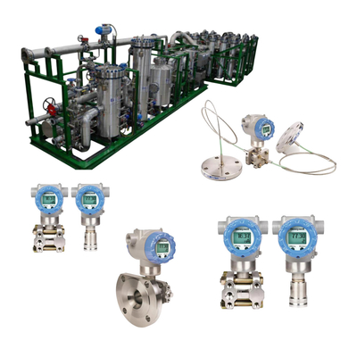
The instrument air source is required as another input to the valve positioner. The air source for the instrument is filtered and regulated through an air filter and regulator to provide clean air to the valve positioner. (In actual working conditions, the pneumatic valve positioner is used because the input air contains impurities or is not clean air, which is a common reason why the pneumatic valve positioner is prone to malfunction.)
Utilizing sufficient instrument air pressure, the valve positioner is able to convert the desired pressure signal into the correct amount of actuator movement.
The positioner also needs to receive feedback to precisely position the valve stem to open and close within the desired range. This feedback is sent from the control valve to the positioner via a mechanical device. In this way, the positioner determines the amount of pressure required to move the stem on the actuator.
What is a valve positioner?
A valve positioner is a device that throttles a control valve to a desired set point.
An input signal and a feedback signal are the two inputs to the valve positioner.
The input signal is the control signal that provides the set point for the positioner, while the feedback signal indicates the current position of the control valve.
The input signal is provided by the bellows of the pneumatic control system. As the input signal increases, the bellows expands and acts on the beam. The beam rotates and moves the baffle associated with the nozzle.
As the position of the baffle changes, the pressure to the nozzle changes accordingly and actuates the pneumatic relay.
At this stage we have a pressure-pressure transducer as an input. To create a positioner, there must be feedback. The feedback confirms that the control valve is responding to the input signal and that the valve position is consistent with the given input signal. Here, mechanical components provide the feedback signal from the control valve to the positioner.
The cam is attached to an arm that rotates with the valve travel. The feedback signal also acts on the beam, creating a reaction force with the input signal in the bellows.
If the input signal to the device increases, the bellows will act on the beam again and move the valve flap closer to the nozzle. As the nozzle and output pressure increase, the valve moves and the feedback from the cam acts on the other side of the beam and moves the flapper away from the nozzle.
The beam is referred to as the summation element. Both input and feedback act on the summation beam and are constantly compared to each other.
If the forces are equal, the relationship between the nozzle and the flapper remains stable and the output pressure of the unit remains constant.
The valve position then remains constant. If one of the forces changes, the valve position is again adjusted to the change in nozzle and output pressure until the two forces are balanced again.
If the positioner is calibrated correctly, the valve position will correspond to the given control signal.
Let's give an example:
Enter a control signal using 3 to 15 PSI.
| Control Signal |
Valve Opening |
Valve Position |
| Air Pressure |
Signal |
| 3PSI |
4mA |
Fully Opened |
0% |
| 9PSI |
12mA |
Half Opened |
50% |
| 15PSI |
20mA |
Fully Closed |
100% |
Referring to the table above.
- With a control signal of 3 PSI, the valve is fully open 0%.
- With a control signal of 9 PSI, the valve travels 50%.
- With a control signal of 15 PSI, the valve is fully closed 100% of the time.
The positioner enables the control valve to overcome valve friction and process forces that can cause valve position deviations.
In addition to stem position, there are many other benefits to using a control valve positioner. High precision positioners are often used to achieve throttling control of piston actuators to accommodate incompatible control signals. Ensuring correct closure of control valves, realizing split-range control, and changing the gain characteristics of control valves.
And there are 3 main types of valve positioners: 1) Pneumatic valve positioners; 2) Electro-pneumatic (EP) valve positioners; and 3) Digital valve positioners. This article here is mainly about the pneumatic valve positioner related work.
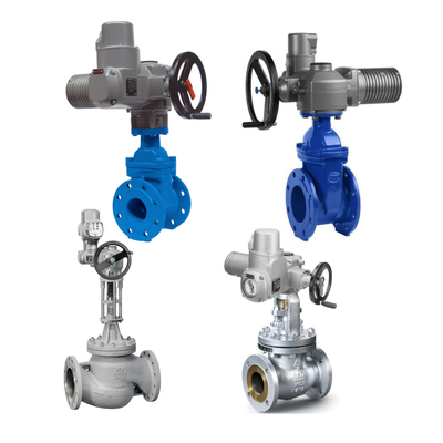
Where is the valve positioner located?
Mounting location of the pneumatic valve positioner:
- In straight stroke control valves, the valve positioner is usually mounted on the outside or top housing of the pneumatic actuator.
- In angle stroke control valves, the valve positioner is usually mounted near the end of the shaft.
The positioner is mechanically connected to the valve stem or spindle.

 Your message must be between 20-3,000 characters!