I. Overview of Intelligent Positioner
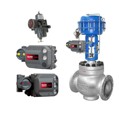
Intelligent valve positioner consists of signal conditioning part, microprocessor, electric-pneumatic conversion control part and valve position detection and feedback device, etc. The input signal can be 4~20mA signal or digital signal.
The signal conditioning part converts the input signal and the valve position feedback signal into a digital signal acceptable to the microprocessor. The microprocessor will be the two digital signals for processing, comparison, judgment of the valve opening and the input signal corresponds to, and output control signal to the electric - gas conversion control part, converted to pneumatic signals to pneumatic actuators, to promote the action of the regulator. The valve position detection and feedback device detects the stem displacement of the actuator and converts it into an electrical signal for feedback to the signal conditioning circuit.
Intelligent valve positioner usually have a liquid crystal display and manual operation button, the display is used to display various status information of the valve positioner, manual operation button is used to input configuration data and manual operation.
Smart valve positioner microprocessor as the core, compared with many analog valve positioner, has the following advantages:
- Intelligent valve positioner mechanical movable parts less, the input signal, feedback signal comparison is digital comparison, not easily affected by the environment, good work stability, there is no mechanical error caused by the impact of the dead zone, so the positioning accuracy and reliability is high.
- Intelligent valve positioner generally contains commonly used linear, logarithmic and fast-open characteristic function module, can be set directly through the button or the host computer, handheld data setter, so the flow characteristics of the modification is convenient.
- Zero adjustment and range adjustment do not affect each other, so the adjustment process is simple and fast. Many varieties of intelligent valve positioner can not only automatically zero and range adjustment, and can automatically recognize the fitted actuator specifications, such as gas chamber volume, the role of the form, etc., automatic adjustment, so that the valve is in the best working condition.
- In addition to the general self-diagnostic function, the intelligent valve positioner can output the feedback signal corresponding to the actual action of the regulating valve, which can be used for remote monitoring of the regulating valve's working status to accept the digital signal of the intelligent type. Valve positioner, with two-way communication capabilities, can be used locally or remotely using a host computer or handheld operator for valve positioner configuration, debugging, diagnostics.
The control signal of intelligent valve positioner is 4~20mA, which usually comes from PLC system, DCS system, PID regulator or handheld operator. For conventional instrumentation, the PID regulator is generally access to the measurement signal of the controlled object, the controlled object, measurement sensors, control valves and PID regulator to form a closed-loop control loop, intelligent valve positioner output of the valve position feedback signal is generally not sent to the PID regulator; control of the valve positioner by the hand manipulator, the hand manipulator can be accessed at the same time to the automatic control signals and intelligent valve positioner output of the valve position feedback signal. The valve positioner is controlled by hand manipulator.
II. Comparison of various brands of positioners to explain
Valve positioner as the main accessory of pneumatic control valves, control valves play an important role in improving the quality of operation. Valve positioner according to the different input signals can be divided into pneumatic valve positioner, electrical valve positioner and intelligent valve positioner. At present, in the production process of chemical enterprises, pneumatic valve positioner and electrical valve positioner use less, more than 95% of the control valve are used to adjust the valve opening smart valve positioner. Smart valve positioner is divided into analog and digital two categories. Analog smart valve positioner receives standard analog current or voltage signals, the analog signal is converted to digital signals as input to the microprocessor, this type of positioner does not have a digital communication function. Digital smart valve positioner to receive digital signals, can be subdivided into two types: Type 1 and analog smart valve positioner is similar, in addition to analog signals converted to digital signals as microprocessor input signals, but also digital signals can be superimposed on the analog signals (such as HART signals), and the transmission of signals on the cable and the analog smart valve positioner the same, but with the digital communication function; Type 2 Digital smart valve positioner directly receives digital signals from the fieldbus, which are converted into working signals for the actuator after processing by the microprocessor.
1, the concept of the positioner
According to the national standard GBIT 22137.1-2008 (equivalent to IEC61514-2000) “industrial process control system with a valve positioner Part 1: pneumatic output valve positioner performance evaluation method" in 3.1 definition: positioner (Positioner) is connected to the final control element or the moving parts of the actuator positioning controller, can automatically adjust the output signal Y supplied to the actuator. Positioner (Positioner) is a positioning controller connected to the final control element or moving part of the actuator, which can automatically adjust the output signal Y supplied to the actuator in order to maintain the pre-desired travel signal X associated with the input signal W. The input signal W can be a pneumatic signal (pneumatic positioner), a current or voltage signal (electrical positioner), a pulse signal, or a digital signal.
According to the national standard GBIT 2900.56-2008 (equivalent to IEC 60050-2006), “Electrotechnical Terminology Control Technology", Article 351-32-25 definition: Positioner (Positioner) is a combination of the final control element of the actuator and the final control element of the actuator mechanical manipulation of the physical unit.
According to the national standard GBT 17212-1998 (equivalent to IEC 902-1987) “Industrial Process Measurement and Control Terms and Definitions" in the P3.3.1.04 definition: Positioner (Positioner) is based on standardized signals to determine the position of the actuator output lever device. The positioner compares the input signal with the mechanical feedback linkage of the actuator and then provides the necessary energy to push the actuator output rod until the output rod position feedback is equivalent to the signal value.
According to the Chinese machinery industry standard JB/T 7368-2015 “industrial process control system with valve positioner" in the definition of 3.1: Valve Positioner (Valve Positioner) is a kind of valve or actuator mechanical connection automatically adjust the output pressure to the actuator to ensure that the valve position and the input signal with the accuracy of the specified relationship of the position controller. This concept is the same as the national standard GB/T 26815-2011 (equivalent to IEC 902-1987) “industrial automation instrumentation terminology actuator terminology," the definition of the valve positioner in Article 2.7.3.
According to the national standard GBIT 22137.2-2008 (equivalent to IEC61514-2000) “industrial process control system with valve positioner Part 2: Intelligent Valve Positioner Performance Evaluation Methods" in the definition of Article 3.1: Intelligent Valve Positioner (Intelligent Valve Positioner) is based on microprocessor technology, digital technology for data processing, decision-making and generation. Digital technology for data processing, decision generation and two-way communication position sensor. It can be equipped with additional sensors and additional functions to support its main functions.
According to the national standard GBIT 26815-2011 (equivalent to IEC902-1987) “Industrial Automation Instrumentation Terminology Actuator Terminology" in the definition of 2.7.7: Intelligent valve positioner (Intelligent valve positioner) is based on microprocessor technology, can receive analog signals or digital signals transmitted through the field bus. The use of digital technology for data processing, with a two-way communication function of a positioner.
2,Pneumatic components of smart valve positioner
Pneumatic components of the smart valve positioner as a key component, its reliability, vibration resistance and power consumption and other indicators will directly affect the performance of the machine. Intelligent valve positioner pneumatic components are generally composed of two parts: I / P converter and power amplifier. I / P converter is a small device to convert the current signal into a pneumatic signal, generally using two technologies: one is based on the principle of the inverse piezoelectric effect of technology; the other is based on the principle of electromagnetism and nozzle baffle mechanism of technology. Due to the I / P converter output flow is very small, so need to be equipped with a power amplifier to amplify the power of the pneumatic signal, generally using a pneumatic amplifier or pneumatic slide valve.
ABB TZIDC, Fisher DVC6200, Samson 3730 intelligent valve positioner in the I / P converter as an example, respectively, based on the electromagnetic principle and the nozzle baffle mechanism of the I / P converter, based on the principle of the inverse piezoelectric effect of the I / P converter (piezoelectric valve) is relatively simple, is not described here.
(1) ABB TZIDC I/P converter
ABB TZIDC I/P converter working principle is shown in Figure 1, ABB TZIDC valve positioner I/P converter will be 4 ~ 20mA standard current signal into 0.2 ~ 1,0bar (3 ~ 15psi) (1bar = 100kPa) pressure signal. When the coil receives the 4~20mA standard current signal, the magnet drives the lever arm to produce micro-displacement of the baffle plate, the gap between the baffle plate and the air nozzle changes, so that the back pressure signal of the air nozzle changes, and then amplified by the amplifier outputs the air pressure signal of 0.2~1,0bar(3~15psi).The output signal of the I/P converter is proportional to the electrical signal.
(2) Fisher DVC6200 I/P Converter
The principle of operation of the Fisher DVC6200 I/P converter is shown in Figure 2. The I/P converter module of the positioner receives the standard DC current input signal from the control device, and clean, oil-free instrument air through the constant throttle orifice (constant air resistance) to the nozzle, the current signal interacts with the coil and magnet to generate force, driving the balance beam to rotate, the balance beam connected to the baffle plate and the gap between the nozzle for the variable air resistance. When increase the drive signal flow through the electromagnetic coil, attract the balance beam action, balance beam drive baffle plate to make it close to the nozzle (change the distance between the baffle plate and the nozzle), resulting in an increase in the back pressure of the nozzle that is sent to the pneumatic amplifier pneumatic signal increases, and ultimately the output of the valve positioner increases in pneumatic pressure; and vice versa, when the drive signal is reduced, through the electromagnetic coil to make the balance beam / baffle plate far away from the nozzle, so that the back pressure decreases, and the output of pneumatic The output of the pneumatic amplifier decreases.
(3) Samson 3730 I/P Converter
The I/P converter of the Samson 3730 operates as shown in Figure 3. The electrical converter of the Samson 3730 consists of an I/P converter module based on the force-balancing principle of operation and a downstream booster. When a DC current signal is applied to the plunger coil, which is located in the magnetic field of a permanent magnet, the force on the balance beam is proportional to the incoming current signal, and the resulting reaction force moves the baffle away from the nozzle. When the air source through the fixed restriction hole, the distance between the baffle plate and the nozzle has changed, making the nozzle back pressure has changed accordingly, at this time, the back pressure of the nozzle acts on the amplifier diaphragm to control the signal air pressure changes, so that the amplifier outputs different flow rate and pressure signals.
3, the working principle of the intelligent valve positioner
Currently used in the domestic market of foreign brands of intelligent valve positioner are: ABBTZIDC, Fisher DVC 6200, Samson 3730, Flowserve logix 520MD, Dresser-MasoneilanSV1-1-AP, Siemens SIPART PS2, Metso- Neles ND9000, IPS-FoxboroSDR960 and SDR991, azibil (Shanwu) SVP7. Neles ND9000, IPS-FoxboroSDR960 and SDR991, azibil (Yamatake) SVP700. the following are discussed below the principle of operation of the nine brands (corresponding models) smart valve positioner.
(1) ABB TZIDC

The principle of operation of the ABB TZIDC is shown in Figure 4. The positioner consists of an electronic module, an I/P module with a 3-position 3-way valve and a position sensor. The microprocessor CPU is the core component of the electronic module, the I/P module with a 3-position 3-way valve is the core component of the current and pneumatic pressure conversion, and the position sensor provides a reliable valve position, which allows the positioner to carry out intelligent control. When the valve positioner is supplied with power, the positioner is processed by the AD converter according to the input signal and the position sensor signal for the CPU to call, and the automatic detection and tuning program stored in the EEPROM is automatically adjusted by the deviation of the set value and the position feedback signal. the I/P module receives the electrical signal from the electronic module, and converts the electrical signal from the positioner into the pneumatic signal to drive the pneumatic actuator. The I/P module receives electrical signals from the electronic module and converts the electrical signals from the positioner into gas signals to drive the pneumatic actuator.
(2) Fisher DvC 6200
Fisher DVC 6200 principle of operation as shown in Figure 5, this digital valve controller housing contains travel sensors, junction boxes, pneumatic input and output connections and a main module, the main module can be easily replaced in the field without disconnecting the field wires or pipelines. The main module contains components such as an I/P converter, pneumatic amplifier, pneumatic amplifier position feedback assembly, printed circuit board (PWB) assembly, and three pressure sensors. The position of the amplifier can be detected by probing a magnet on the amplifier beam with a detector on the printed circuit board. The travel sensors are used for small loop feedback readings.
Fisher DVC 6200 digital valve controllers are loop-powered instruments that provide valve position control proportional to the input signal from the control room. The input signal is routed through a twisted pair cable to a junction box, into a printed circuit board assembly submodule, where it is read, calculated, and converted by a microprocessor into an analog I/P drive signal to drive an I/P converter.
As the input signal increases, the drive signal to the IP converter increases, and the output air pressure from the IP converter increases. the output air pressure from the I/P converter is sent to the pneumatic amplifier sub-module, which is also connected to the air pressure source and amplifies the pneumatic signal from the IP converter. The pneumatic amplifier receives the amplified pneumatic signal and provides two air pressure outputs. As the input air pressure increases (4~20mA signal), the air pressure at Output A will always increase, while the air pressure at Output B will always decrease. The air pressure at output port A is used in double-acting and single-acting positive-acting applications, and the air pressure at output port B can be used in reverse, double-acting and single-acting applications. An increase in air pressure at Outlet A will drive the actuator pushrod downward. The actuator position is detected by a non-contact travel feedback sensor. The actuator continues to move downward until it reaches the correct actuator position.
At this point, the printed circuit board assembly will stabilize the I/P drive signal. This will position the baffle to prevent further increase in nozzle pressure.
As the input signal decreases, the drive signal to the IP converter decreases and the output air pressure to the I/P converter decreases. The pneumatic amplifier decreases the air pressure at outlet A and increases the air pressure at outlet B. The actuator continues to move upwards until it reaches the I/P converter. The actuator continues to move upward until it reaches the correct actuator position. At this position point, the printed circuit board assembly will stabilize the I/P drive signal. This will position the baffle to prevent further increase in nozzle pressure.
(3) Samson 3730
Samson 3730 principle of operation as shown in the figure, the positioner is mainly composed of an electronic unit with microprocessor, analog electrical converter, output pneumatic amplifier and valve position a resistance linear conversion of the valve position sensor. Positioner installed in the pneumatic control valve, the input control signal will be accurate positioning of the valve. The positioner will control system or controller to the DC input control signal (such as 4 ~ 20mA) as a given value w, control valve stem position through the feedback lever to the valve position sensor, converted into an electrical signal added to the analog PD controller as a regulated parameter or feedback x, the positioner will be compared between the two and according to a certain law output signal y to the pneumatic actuator to adjust the valve position. When there is a control deviation, the PD controller output is changed so that the electrical converter output is changed and the pneumatic actuator of the control valve is pressurized or relieved through the pneumatic amplifier. This change in output signal moves the valve position to a position that corresponds to the input control signal. A flow rate setter with a fixed setpoint allows a constant volume of air to be evacuated for positive pressure purge in the valve positioner housing and ensures fast, trouble-free response of the pneumatic amplifier. The pneumatic amplifier and pressure setter receive the air supply, and the pressure setter provides a constant upstream pressure to the I/P converter module independent of the air supply pressure.
(4) Flowser logix 520MD
The Flowser logix 520MD works as shown in Fig. It is a digital intelligent positioner with integrated HART communication protocol. The positioner consists of three main parts: a microprocessor-based electronic control module, a piezoelectric valve-based electrical converter module and a valve position sensor.
The entire control loop of the logix 520MD positioner can receive either 4-20mA signals (with HART overlay) or digital signals. logix 520MD utilizes two algorithms to process the signals, an internal loop (pilot amplifier control) and an external loop (stem position control). The stem position sensor provides a measurement of the actual position of the stem, and if there is any deviation, the positioner's control algorithm sends a signal to the internal loop control based on the deviation, and the internal loop quickly adjusts the slide valve position. The actuator pressure changes and the valve stem begins to move. The stem movement reduces the deviation between the final command and the stem position, and this process continues until the deviation becomes zero.
The internal circuit controls the position of the slide valve via a drive module. The driver module consists of a Hall effect sensor with temperature compensation and a piezo valve pressure regulator. The piezo pressure regulator controls the air pressure under the diaphragm by bending a piezo beam. The piezoelectric beam deflects with the voltage applied by the inner ring electronics. When the voltage to the piezo valve is increased, the piezo beam bends and closes against the nozzle causing the pressure under the diaphragm to increase. As the pressure under the diaphragm increases or decreases, the slide valve or poppet valve moves up or down, respectively. A Hall effect sensor transmits the position of the slide valve or poppet valve back to the internal electronics for control.
(5) Dresser-Masoneilan SVI-Il-AP
The Dresser-Masoneilan SV1-II-AP Smart Valve Positioner works as shown in the figure. When SV1-II-AP intelligent valve positioner is correctly installed to the control valve, the input control signal (circuit power) and the gas supply is connected, the positioner receives the electrical control signal (4-20mA signal or digital signal) from the controller or other equipment, the microprocessor in the electronic module reads the input control signal (the valve position set value) and compares it with the travel/turn signal of the valve position sensor, and the deviation between the two is calculated as a nonlinear deviation. The deviation of the two according to the non-linear PID algorithm for processing, output to the electromagnetic coil of the I / P electrical converter (nozzle baffle structure), causing changes in the air gap between the nozzle baffle, which in turn becomes the corresponding pre-positioning gas signal p, and then amplified by the pneumatic amplifier gas, so that the pneumatic output p, change, output to the pneumatic actuator to drive the actuator / valve stem to the set position. When the actual valve position is the same as the set valve position, the system stabilizes and the actuator will no longer move. In case of double-acting pneumatic output, the pneumatic component can also be equipped with a reverse output amplifier (output p,) to form a double-acting output to the cylinder type pneumatic actuator.
(6) Siemens SIPART PS2
The working principle of Siemens SIPART PS2 is shown in Fig. 9. When the positioner is connected to the power supply and the control signal, the feedback signal x from the valve stem is converted into a voltage signal and sent to the microprocessor after AD conversion. The controller output signal x is also converted by AD and sent to the microprocessor. The microprocessor calculates the deviation between the two signals and outputs +Δy or -Δy to control the opening and closing of the piezoelectric valve. The operation of the subcontrol loop is realized within the microprocessor, the output of the subcontroller is digital, and the output signal is directly used as the input of the piezoelectric switching valve, which is controlled by pulse-width modulation (time-proportional control). When the control deviation is large, the positioner outputs a continuous signal; when the deviation is not large, it outputs a pulse signal; when the deviation is very small, it outputs a smaller pulse signal; when the deviation reaches the range of the valve control accuracy, there is no output of the control command, and the positioning is maintained.
(7) Metso-Neles ND9000
Metso-Neles ND9000 works as shown in the figure. When the positioner is connected to the power supply and air source, the microcontroller (μC) reads the input signals as well as the valve position sensor signals (a), the pressure sensor signals (Ps, P1, Pz), and the slide valve position sensor signal (SPS). When the microcontroller detects a difference between the input signals and the valve position sensor signals, the microcontroller performs calculations based on the built-in algorithms, and then changes the coil current of the preamplifier valve (PR) to change the guiding pressure of the slide valve (SV). When the guiding pressure of the slide valve decreases, the slide valve moves and the pressure at both ends of the cylinder changes accordingly. The slide valve opens to allow compressed air to enter the drive end of the cylinder and expel the gas at the other end. The increase in air pressure moves the diaphragm piston, and the actuator and feedback lever rotate clockwise. After the valve position sensor detects the rotation angle of the feedback lever, the control algorithm in the microcontroller calculates a new guiding current and continues to adjust until there is no difference between the new position of the actuator and the input signal.
(8) IPS-Foxboro SDR960 and SDR991
The IPS-Foxboro SDR960 and SDR991 work as shown in the figure. They are intelligent valve positioners with 4-20 mA or HART signals, which are supplied to the electronics internally via a voltage converter. The analog input signals are connected to the digital controller via A/D converters and switches. Smart valve positioners with Profibus PA or Foundation Fieldbus are connected via a bus and the digital signals are connected to the digital controller via an interface kit. The output signal of the digital controller drives the electrical converter (I/P module), which in turn controls the preamplifier and the single- (or double-) acting pneumatic power amplifier. The pneumatic power amplifier outputs a pneumatic signal (y) to the actuator, which must be supplied with a 1.4 to 6.0 bar (20 to 90 psi) air supply. The position feedback signal (x) of the actuator is sent to the control unit through the position sensor.
The Smart Valve Positioner is available with the following accessories on request: pressure gauge, pressure switch, 4-20mA feedback output, alarm module and mechanical limit switches.
(9)azibil SVP700
azibil (Yamatake) SVP700 principle of operation as shown in the figure, this is a configuration of the microprocessor intelligent valve positioner. svp700 series of positioner is mainly composed of microprocessor, digital control module, power supply module, AD converter module, pneumatic components (I / P electrical converter and pneumatic amplifiers) and the valve position sensor components. The control valve stem is connected to the positioner feedback lever, and the valve position travel is transmitted to the non-contact magnetoresistive sensor for measurement through the feedback lever. At the same time, the valve positioner receives 4~20mA DC control signal, compares the valve position obtained by the algorithm according to the configuration with the measured valve position signal and performs the operation to derive the positioning drive signal and passes it to the EPM drive device, and then outputs the pneumatic signal through the conversion of the pneumatic components (I/P electrical converter and pneumatic amplifier) to the pneumatic actuator to control the valve position.
The working principle of each type of valve positioner is similar. These nine brands of positioners are foreign products, but in fact the domestic positioner configuration mode is basically the same.
4, intelligent valve positioner part of the technical indicators comparison
(1) Comparison of indicators
Through the query of the above nine foreign brands of intelligent valve positioner technical information, part of the technical indicators are summarized, the results are shown in Exhibit 1.
(2) Parameter description
Pneumatic components. The power amplifier uses a pneumatic slide valve or pneumatic amplifier. Only Flowserve's logix 520MD and Siemens' SIPART PS2 positioners use piezo valves made on the piezoelectric principle as the electrical conversion element.
Air supply pressure (single-acting, for example). The air pressure (for example, single-acting) of smart valve positioners basically ranges from 1.4 to 7.0 bar (20 to 102 psi), except for Emerson-Fisher's DVC 6200, which has an air pressure of up to 10 bar.
Air quality. The quality of instrument air used for the above smart valve positioners meets the requirements of ISO 8573-1 “Compressed Air Part 1 Contaminants and Cleanliness Levels" or ISA7.0.01 “Instrument Air Quality Standards". The larger the value of the Maximum Solid Particle Class of the compressed air, the larger the size of the solid particles contained in the compressed air. The larger the value of the oil content class of compressed air, the larger the total oil content (oil aerosol, oil liquid and oil vapor) of compressed air. The greater the value of the pressure dew point rating of the compressed air, the greater the water content of the compressed air. Specifically described as follows.
- particle size indicators
Emerson-Fisher's DVC 6200 can reach class 7 index, Dresser-Masoneilan's SV1-I-AP can reach class 6 index, Metso-Neles' ND9000 can reach class 5 index, while Siemens' SIPARTPS2 and IPS-Foxboro's SDR960 and SDR991 only have class 2 index. SIPARTPS2 of Siemens and SDR960 and SDR991 of IPS-Foxboro have only 2 levels, which means that Siemens and IPS-Foxboro's positioners require too high a particle size quality of the instrument air, and when the quality of the instrument air decreases, the performance and regulation of the positioners will be affected. Other brands of positioner particle size indicators are mostly in the 4 level (including) or more.
- Oil content
Siemens' SIPART PS2 oil content index is level 2, which means that the positioner on the instrument air oil content requirements are too high, and other brands of positioners are in the oil content of level 3 or above.
- Dew point
In comparison, the first three positioners have a low dew point requirement, while Siemens' SIPART PS2 positioner has a high dew point requirement.
The production plant uses a large number of intelligent valve positioners, and long-term working condition. When the positioner on the instrument gas quality requirements are too high, in the abnormal state (instrument gas quality decline) is prone to clogging, water and other phenomena, affecting the normal operation of the valve. When the positioner of important valves lose control function will produce fatal injury. Through the actual field use, Emerson-Fisher's DVC 6200Dresser-Masoneilan's SV1-II-AP, Samson's 3730 and ABB's TZIDC and other positioners have stable performance, precise control and low failure rate; while Siemens positioners have a high failure rate, easy to enter the water, low precision.
Maximum output capacity (single-acting, for example). The maximum output capacity of the valve positioner directly affects the speed of valve action (switching time). Table 1 shows that: Emerson-Fisher's DVC 6200 outputs 29.5Nm3/h of instrument gas at a source pressure of 5.5bar (80psi); Dresser-Masoneilan's SV1-I-AP outputs 660L/min (39.6Nm3/h) of instrument gas at a source pressure of 6.2bar (90psi). Nm3/h) instrument air; Flowser's logix520 outputs 20.8 Nm3/h instrument air at an air pressure of 4.1 bar (60 psi). Other brands of positioners output about 10Nm3/h of instrument air at an air pressure of 6.0bar (90psi).
Air consumption. The positioner itself will consume a certain amount of instrument air during operation. Table 1 shows that the positioner's consumption of instrument air is very low, but Emerson-Fisher's DVC 6200 and Dresser-Masoneilan's SV1-I-AP positioners consume more air than other positioners.
Operating Ambient Limiting Temperature (not specifically selected). All brands of positioners in this document have operating ambient temperatures ranging from -40 to 80°C under non-special selection (conditions).
LCD display. Valve positioner in the control process, field inspectors sometimes need to observe the valve valve position, only Emerson-Fisher's DVC 6200 does not have LCD display function.
Protection ratings. All of the above valve positioners are IP66 rated.

 Your message must be between 20-3,000 characters!