Pneumatic Control Valve Response Problems: Instrument Air, Tubing, and Positioner Diagnostics
Introduction
A pneumatic control valve that responds slowly or fails to follow its control signal can affect the entire process. Flow may take too long to stabilize, pressure may fluctuate, or the valve may remain in one position despite a change in the controller output.
These symptoms are not always caused by a faulty valve positioner. Instrument air quality, supply pressure, tubing restrictions, actuator condition, and mechanical friction can all influence valve response.
A systematic troubleshooting process helps maintenance teams identify the source of the problem before replacing components or changing control settings.
1. Check Instrument Air Supply First
Instrument air provides the energy required to operate many pneumatic control valves. If the supply pressure is too low or unstable, the actuator may not develop enough force to move the valve as required.
Typical warning signs include slow travel, incomplete stroke, inconsistent response, and problems that become more noticeable when several pneumatic devices operate simultaneously.
Start by checking:
-
Whether the supply pressure meets the requirements of the installed positioner and actuator.
-
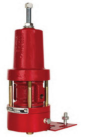
Whether the filter regulator is blocked, damaged, or incorrectly adjusted.
-
Whether pressure drops occur during valve movement.
-
Whether the air supply contains excessive moisture, oil, or particles.
-
Whether the supply line is shared with other equipment that creates large demand changes.
Do not increase supply pressure beyond the permitted limits of the positioner, actuator, and associated accessories. The correct setting must be based on the equipment specifications.
2. Inspect Tubing, Fittings, and Airflow Restrictions
Even when the supply pressure is correct, restrictions between the positioner and actuator can delay valve movement.
Undersized tubing, obstructed fittings, damaged hoses, excessive tubing length, and restricted solenoid valves can limit the rate at which air enters or leaves the actuator.
A valve may therefore move slowly in one direction, respond unevenly, or take longer to reach the commanded position.
Inspect the pneumatic connections for leakage, kinks, contamination, and incorrect routing. Check whether the installed tubing and fittings meet the requirements of the equipment manufacturer.
Simply increasing the supply pressure may not solve a restriction problem. The air path itself must be checked.
3. Evaluate the Valve Positioner
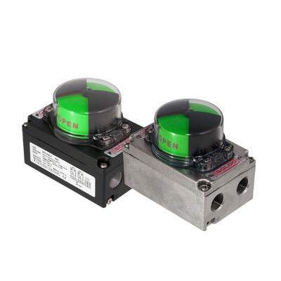
A positioner compares the requested valve position with its feedback and adjusts the pneumatic output to move the actuator.
If the positioner is incorrectly configured, poorly mounted, or unable to receive a reliable input signal, the valve may not follow the command accurately.
Common checks include:
-
Confirming the input signal and configured operating range.
-
Verifying that travel feedback corresponds to actual valve movement.
-
Checking mounting alignment and linkage condition where applicable.
-
Reviewing alarms, diagnostic messages, and actuator pressure readings if supported.
-
Confirming that the positioner configuration matches the actuator action and valve travel.
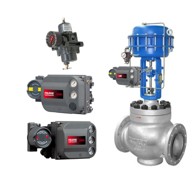
For example, Fisher FIELDVUE DVC6200 digital valve controllers provide configuration and diagnostic functions that can assist with troubleshooting. Other digital positioners, such as Masoneilan SVI or Neles ND9000 models, may offer comparable diagnostic capabilities depending on the version and configuration.
A diagnostic alarm is a useful clue, not a complete diagnosis. Always compare electronic information with the physical behavior of the valve assembly.
4. Check Actuator Performance and Mechanical Friction
The actuator must produce enough force to overcome the valve's operating resistance under actual process conditions.
If the required force is too high, or the actuator has an internal problem, the valve may move slowly or fail to complete its stroke.
Possible causes include:
-
Insufficient actuator output.
-
Damaged diaphragm or seals.
-
Internal leakage.
-
Spring problems in spring-return actuators.
-
Excessive packing friction.
-
Misalignment between the actuator and valve.
-
Deposits, corrosion, or wear in moving components.
If the positioner output changes but the actuator does not respond as expected, the problem may be downstream of the positioner rather than in the control signal itself.
Mechanical inspection and stroke testing should follow the manufacturer's procedures and appropriate process isolation requirements.
5. Distinguish Slow Response from Stiction
Slow response and stiction can produce similar symptoms, but the troubleshooting approach differs.
A valve with slow response may move continuously but take too long to reach the commanded position. Restricted airflow, low supply capacity, or a slow actuator can be contributing factors.
A valve with stiction may remain stationary while the command changes, then move suddenly when the available force overcomes static friction.
Reviewing the command signal, actual travel, and actuator pressure together can help distinguish these patterns. Where supported, positioner diagnostics or a controlled stroke test can provide additional information.
Avoid adjusting positioner tuning to hide severe mechanical friction. Excessive tuning changes may create instability without resolving the underlying problem.
6. A Step-by-Step Troubleshooting Sequence
Use the following sequence to narrow down the likely cause:
Step 1: Confirm the symptom. Determine whether the valve is slow, unstable, unable to complete its stroke, or failing to track the command.
Step 2: Check the control signal. Confirm that the positioner receives the expected input and that the controller output is changing as intended.
Step 3: Verify instrument air. Check supply pressure, regulator condition, air quality, and pressure stability during movement.
Step 4: Inspect pneumatic connections. Look for leakage, restrictions, damaged tubing, and unsuitable fittings.
Step 5: Review positioner status. Check configuration, travel feedback, alarms, and supported diagnostics.
Step 6: Evaluate the actuator and valve. Investigate friction, mechanical damage, actuator output, and valve operating resistance.
Step 7: Test the complete assembly. After corrective work, verify movement across the required travel range and confirm that the response meets the application's needs.
This sequence helps avoid replacing a positioner when the actual cause is an air-supply restriction, mechanical friction, or actuator problem.
7. When Should Components Be Replaced?
Replacement is appropriate when testing identifies a defective or unsuitable component, not simply because the valve responds poorly.
Depending on the findings, the required work may involve servicing the filter regulator, repairing pneumatic tubing, correcting mounting issues, maintaining the actuator, recalibrating the positioner, or replacing a failed component.
Before ordering a replacement positioner, verify the valve mounting arrangement, actuator type, travel, input signal, air supply requirements, communication protocol, and required accessories. Matching only the product model or external appearance may not be sufficient.
Conclusion
Pneumatic control valve response problems can originate in the instrument air system, pneumatic connections, positioner, actuator, or valve mechanics. Checking these elements in a logical sequence is usually more effective than replacing parts based on symptoms alone.
Reliable troubleshooting starts with observing the relationship between the control command, actual valve travel, and pneumatic pressure. This provides a clearer basis for deciding whether adjustment, maintenance, or component replacement is required.
Need assistance with a pneumatic control valve or positioner replacement? Provide the existing model, actuator type, input signal, air supply conditions, and symptoms to help identify a suitable solution.


 Your message must be between 20-3,000 characters!