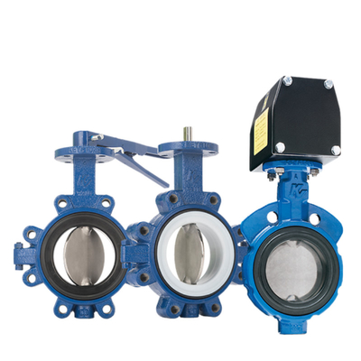
Pneumatic control valve is one of the industrial process control instruments widely used in petroleum, chemical, electric power, metallurgy and other industrial enterprises. Chemical production control valve in the regulation system is essential, it is composed of industrial automation system is an important link, it such as production process automation of the hands and feet.
Working Principle
Pneumatic control valve is to compressed air as a power source, the cylinder as an actuator, and with the help of electrical valve positioner, converter, solenoid valve, holding valve and other accessories to drive the valve, to realize the switching or proportional adjustment, receiving industrial automation control system control signals to complete the adjustment of pipeline media: flow, pressure, temperature and other process parameters. Pneumatic control valve is characterized by simple control, fast response, and intrinsically safe, without the need to take additional explosion-proof measures.
Pneumatic control valve working principle

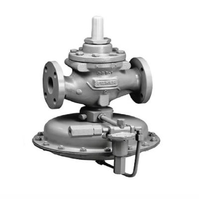
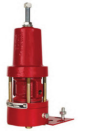
Pneumatic control valves are usually composed of pneumatic actuators and control valves connected to the installation and commissioning, pneumatic actuators can be divided into single-acting and double-acting two kinds of single-acting actuators have reset springs, while double-acting actuators do not have reset springs. Single-acting actuator, which can be in the loss of origin or sudden failure, automatic homing to the valve initially set to open or close state.
Pneumatic control valve according to the action form of gas open type and gas shut type two kinds, that is, the so-called normally open and normally closed type, pneumatic control valve gas open or gas shut, usually through the positive and negative action of the actuator and the valve state structure of the different assembly way to realize.
Pneumatic control valve mode of action
Air-open type (normally closed type) is when the air pressure on the diaphragm head increases, the valve acts in the direction of increasing the opening, and when the upper limit of the input air pressure is reached, the valve is in the fully open state. Conversely, when the air pressure decreases, the valve moves in the direction of closing, and when there is no input air, the valve is fully closed. Gu usually we call the air-open type regulating valve as the fault closure type valve.
The air-closed type (normally open type) operates in exactly the opposite direction to the air-open type. When the air pressure increases, the valve to close the direction of action; air pressure decreases or no air pressure, the valve to open the direction or full open until. Gu usually we call the air off type regulating valve for failure to open type valve.
The choice of air open and air closed is based on the safety of process production point of view to consider. When the gas source is cut off, whether the regulating valve is in the closed position or the open position is safe.
For example, a heating furnace combustion control, control valves installed in the fuel gas pipeline, according to the temperature of the furnace chamber or the temperature of the heated material in the furnace outlet to control the supply of fuel. In this case, it is preferable to use a gas-open valve to be safer, because once the gas supply is stopped, it is more appropriate for the valve to be closed than for it to be fully open. If the gas supply is interrupted, the fuel valve is fully open, will make the danger of overheating. Another example is a cooling water cooled heat transfer equipment, hot materials in the heat exchanger and cooling water for heat exchange is cooled, the control valve is installed in the cooling water pipe, with the temperature of the material after the heat transfer to control the cooling water, in the interruption of the gas supply, the control valve should be in the open position safer, it is preferable to choose the gas shut-off (i.e., FO) control valve.
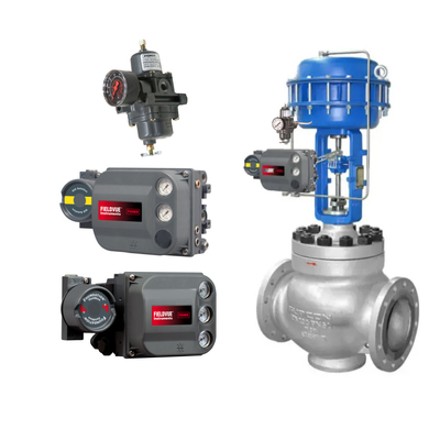
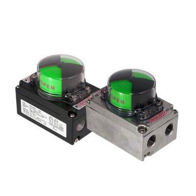
Valve Positioner
Valve positioner is the main accessory of the control valve, and pneumatic control valve greatly supporting the use of the regulator, it accepts the regulator's output signal, and then its output signal to control the pneumatic control valve, when the regulator valve action, the displacement of the valve stem and through the mechanical device feedback to the valve positioner, the valve position status through the electrical signal to the upper system. Valve positioner according to its structural form and working principle can be divided into pneumatic valve positioner, electric - gas valve positioner and intelligent valve positioner.
Valve positioner can increase the output power of the regulating valve, reduce the transmission hysteresis of the regulating signal, accelerate the movement speed of the valve stem, can improve the linearity of the valve, overcome the friction of the valve stem and eliminate the influence of the unbalance force, so as to ensure the correct positioning of the regulating valve.
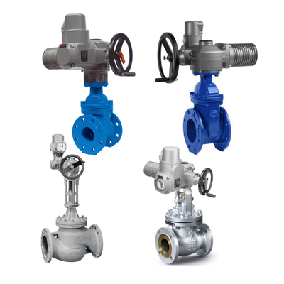
The actuator is divided into pneumatic actuators, electric actuators, straight stroke, angle stroke. It is used to open and close all kinds of valves, wind boards, etc. automatically and manually.
Pneumatic control valve installation principles
- Pneumatic control valve installation position, from the ground requires a certain height, the valve should leave a certain space above and below, in order to carry out valve disassembly and repair. For equipped with pneumatic valve positioner and handwheel control valve, must ensure that the operation, observation and adjustment is convenient.
- Control valve should be installed in the horizontal pipeline, and up and down with the pipeline perpendicular to the general valve to be supported to ensure stable and reliable. For special occasions, the need for horizontal installation of the control valve in the vertical pipeline, the control valve should also be supported (except for small diameter control valve). Installation, to avoid additional stress to the control valve).
- The working environment temperature of the control valve should be (-30 ~ + 60) Relative humidity is not greater than 95% 95% , relative humidity is not greater than 95%.
- Control valve before and after the position should be straight pipe section, the length of not less than 10 times the diameter of the pipe (10D), in order to avoid the valve's straight pipe section is too short and affect the flow characteristics.
- The caliber of the control valve and process piping is not the same, should be connected using a reducer. In the installation of small caliber control valve, threaded connection can be used. Fluid direction arrow on the valve body should be consistent with the fluid direction.
- To set up bypass piping. The purpose is to facilitate switching or manual operation, can be in the case of non-stop maintenance of the control valve.
- Control valves should be thoroughly removed from the pipeline before installation of foreign objects, such as dirt, welding slag.
Common Failures and Handling
-
Control valve does not operate
First confirm whether the air source pressure is normal, find the air source failure. If the air source pressure is normal, then determine the positioner or electric/gas converter amplifier output; if no output, the amplifier constant throttle hole is blocked, or moisture in the compressed air accumulated in the amplifier ball valve. Use a small steel wire to unclog the constant throttle hole, remove the dirt or clean the air source.
If all of the above are normal, there is a signal but no action, then the actuator failure or valve stem bending, or spool stuck. In this case, the valve must be removed for further inspection.
-
Control valve jammed
If the valve stem reciprocating stroke action is sluggish, the valve body or viscous substances, coking blockage or packing pressure is too tight, or PTFE packing aging, valve stem bending scratches. Control valve jamming faults occur mostly in the new into operation system and overhaul the initial operation, due to pipeline welding slag, rust, etc. in the throttle port and guide parts caused by blockage so that the medium flow is not smooth, or control valve overhaul packing is too tight, resulting in increased friction, resulting in a small signal does not move, the phenomenon of the big signal action is too much.
Encountered such a situation, you can quickly open and close the secondary line or regulating valve, so that the spoils from the secondary line or regulating valve washed away by the media. In addition, you can also use a pipe wrench to clamp the valve stem, in the case of external signal pressure, positive and negative force spinning valve stem, so that the spool flashed over the card. If the problem can not be solved, you can increase the pressure of the gas source, increase the driving power to move up and down repeatedly a few times, you can solve the problem. If you still can not move, you need to do disassembly of the control valve, of course, this work requires strong professional skills, must be completed with the assistance of professional and technical personnel, otherwise the consequences are more serious.
-
Valve leakage
Regulating valve leakage generally have regulating valve leakage, packing leakage and spool, seat deformation caused by the leakage of several cases, are analyzed below.
- valve leakage
Stem length is not suitable, gas valve stem is too long, stem up (or down) distance is not enough, resulting in a gap between the spool and seat, can not be fully contact, resulting in poor and internal leakage. The same gas shut-off valve stem is too short, can also lead to a gap between the valve spool and seat, can not be fully contact, resulting in off not tight and internal leakage. Solution: should shorten (or extend) the valve stem so that the length of the valve is appropriate, so that it is no longer internal leakage.
- packing leakage
After the packing is loaded into the packing box, axial pressure is exerted on it by the gland. Due to the plastic deformation of the packing, so that it produces radial force, and close contact with the valve stem, but this contact is not very uniform, some parts of the contact is loose, some parts of the contact is tighter, and even some parts of the contact is not at all on. Control valve in the process of use, the valve stem with the packing between the existence of relative movement, this movement is called axial movement. In the process of use, with the high temperature, high pressure and permeability of the fluid medium, the regulating valve packing box is also a leakage phenomenon occurs more parts. The main cause of packing leakage is the interface leakage, for textile packing will also appear leakage (pressure medium along the packing fibers between the tiny gap to the outside leakage). Valve stem and packing interface leakage is due to the gradual decay of packing contact pressure, packing aging and other reasons, then the pressure medium will be along the packing and the stem of the contact gap between the leakage to the outside.
In order to make the packing into the convenient, chamfered at the top of the stuffing box, in the bottom of the stuffing box placed in the corrosion-resistant gap smaller metal protection ring, pay attention to the protection of the ring and filler contact surface can not be beveled, in order to prevent the filler by the media pressure to push out. Stuffing box and filler contact part of the surface to be finishing, in order to improve the surface finish, reduce filler wear. Filler selection of flexible graphite, because of its good airtightness, friction, long-term use of small changes, wear and tear of the burnout is small, easy to repair, and the gland bolts re-tightened friction does not change, good pressure resistance and heat resistance, not subject to the erosion of the internal medium, and the stem and filler box of the internal contact of the metal does not occur pitting or corrosion. In this way, effectively protect the stem packing box seal, to ensure the reliability of the packing seal, the service life is also greatly improved.
- the valve spool, valve seat deformation leakage
Valve spool, valve seat leakage is mainly due to the casting or forging defects in the production process of control valves can lead to corrosion enhancement. The passage of corrosive media, fluid media scouring will also cause leakage of the control valve. Corrosion mainly in the form of erosion or cavitation. When the corrosive medium through the regulating valve, it will produce on the spool, seat material erosion and impact, so that the spool, seat oval or other shapes, over time, resulting in the spool, seat mismatch, there is a gap, off not tight and leakage occurs.
Put a good valve spool, valve seat material selection off. Select corrosion-resistant materials, the existence of pitting, trachoma and other defects in the product should be firmly removed. If the valve core, valve seat deformation is not too serious, available fine sandpaper grinding, eliminate traces, improve the sealing finish, in order to improve the sealing performance. If the damage is serious, the valve should be replaced with a new one.
-
Vibration
The spring stiffness of the control valve is not enough, the output signal of the control valve is not stable and sharp changes are easy to cause the control valve oscillation. There are selected valve frequency and system frequency or pipeline, base vibration, so that the control valve vibration. Improper selection, control valve work in a small degree of opening there is a drastic flow resistance, flow rate, pressure changes, when more than the valve stiffness, stability deterioration, serious oscillation.
As the causes of oscillation is multi-faceted, to analyze specific problems. Slight vibration, can increase the stiffness to eliminate, such as the choice of large stiffness spring control valve, change the piston implementation structure, etc.; pipeline, base vibration, can be increased by increasing the support to eliminate the vibration interference; valve frequency and the frequency of the system is the same as the replacement of different structures of the regulator valve; work in the small degree of openness caused by the vibration, it is the selection of improperly caused by the valve specifically due to the valve's flow capacity of the value of C is too large, it must be Re-selection, select the flow capacity C value is smaller or the use of split-range control or the use of sub-mother valve to overcome the oscillation generated by the regulating valve working in a small degree of openness.
-
Noisy control valves
When the fluid flows through the control valve, such as before and after the pressure difference is too large will produce for the valve spool, valve seat and other parts of the cavitation phenomenon, so that the fluid produces noise. The value of the flow capacity is selected, the value of the flow capacity must be re-selected to the appropriate value of the regulating valve to overcome the regulating valve working in a small degree of noise caused by the noise, the following are introduced to eliminate the noise of several methods.
- eliminate resonance noise method
Only when the control valve resonance, there is energy superposition and produce more than 100 decibels of strong noise. Some show strong vibration, noise is not big, some weak vibration, but the noise is very big; some vibration and noise are bigger. This noise produces a monotone sound, whose frequency is generally 3000 to 7000 Hz. Obviously, the elimination of resonance, noise naturally disappears.
- to eliminate the noise method of vapor corrosion
Cavitation is the main hydrodynamic noise source. Cavitation, vapor bubble rupture generates high-speed impact, resulting in strong local turbulence, resulting in cavitation noise. This noise has a wide frequency range, generating grating sound, and the fluid contains gravel issued by the sound is similar. Eliminate and reduce cavitation is an effective way to eliminate and reduce noise.
- the use of thick-walled pipe line method
The use of thick-walled pipe is one of the acoustic circuit processing methods. The use of thin-walled can make the noise increase of 5 decibels, the use of thick-walled pipe can make the noise reduction of 0 to 20 decibels. The thicker the wall of the same pipe diameter, the larger the diameter of the same wall thickness, the better the effect of noise reduction. Such as DN200 pipe, the wall thickness of 6.25, 6.75, 8, 10, 12.5, 15, 18, 20, 21.5mm, can reduce the noise were -3.5, -2 (i.e., increase), 0, 3, 6, 8, 11, 13, 14.5 decibels. Of course, the thicker the wall the higher the cost.
- the use of sound-absorbing materials method
This is also a more common, the most effective way to deal with the sound path. Available sound-absorbing materials can be wrapped around the noise source and the pipeline after the valve. It must be pointed out that the noise will be spread by fluid flow and long distance, so the sound-absorbing material package to where, using thick-walled pipe to where, to eliminate the effectiveness of the noise to where the termination. This approach applies to the noise is not very high, the pipeline is not very long, because it is a more costly approach.
- series silencer method this method
Applicable as an aerodynamic noise silencer, it can effectively eliminate the noise within the fluid and inhibit the transmission to the solid boundary layer of the noise level. For high mass flow rate or high pressure drop ratio before and after the valve, this method is the most effective and economical. Significant noise reduction can be achieved by using absorption type series silencers. However, from economic considerations, generally limited to attenuation to about 25 dB.
- soundproof box method
The use of soundproof boxes, houses and buildings, the noise source is isolated inside, so that the noise of the external environment is reduced to a range acceptable to people.
- Series throttling method
In the regulating valve pressure ratio is high (△ P / P1 ≥ 0.8) occasions, the use of series throttling method, that is, the total pressure drop is dispersed in the regulating valve and the valve after the fixed throttling element. Such as the use of diffusers, porous restrictor plates, which is the most effective of the noise reduction methods. In order to get the best diffuser efficiency, must be based on the installation of each piece to design the diffuser (entity shape, size), so that the noise level generated by the valve and the noise level generated by the diffuser is the same.
- the selection of low-noise valve
Low noise valve according to the fluid through the spool, the valve seat of the zigzag flow path (multi-orifice, multi-channel) of the gradual deceleration to avoid any point in the flow path to produce supersonic speed. There are various forms and structures of low-noise valves (designed for specialized systems) for use. When the noise is not very large, the choice of low noise sleeve valve, can reduce the noise 10 to 20 dB, which is the most economical low noise valve.
Valve positioner failure
- Because of the mechanical force balancing principle work, it has more movable parts, easy to be affected by temperature and vibration, resulting in fluctuation of the regulating valve;.
- Adopting nozzle baffle technology, due to the small nozzle hole, it is easy to be blocked by dust or unclean air source, so that the positioner can not work properly;.
- Using the principle of force balance, the spring's elasticity coefficient will change in the bad site, resulting in the nonlinearity of the regulating valve leading to a decline in the quality of control.
- Intelligent positioner consists of microprocessor (CPU), A/D, D/A converter and other components, its working principle is very different from the ordinary positioner, the comparison of the given value and the actual value of the purely electric signals, and no longer force balance. Therefore, it can overcome the disadvantage of force balance of conventional positioner. However, when used for emergency stopping occasions, such as emergency shut-off valve, emergency venting valve, etc., these valves are required to be stationary in a certain position, only when an emergency situation arises, you need to reliably act, long stay in a certain position, it is easy to make the electrical converter out of control resulting in a small signal does not act in a dangerous situation. In addition. Used for the valve position sensing potentiometer due to work in the field, the resistance value is prone to change resulting in a small signal does not act, the large signal is fully open dangerous situation. Therefore, in order to ensure the reliability and availability of intelligent positioners, they must be tested frequently.

 Your message must be between 20-3,000 characters!