Pneumatic diaphragm control valves structure and working principle
Structure of Pneumatic Diaphragm Control Valves:
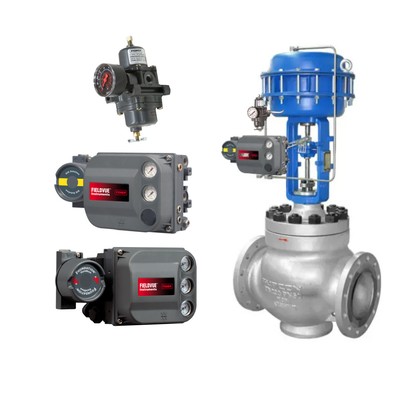
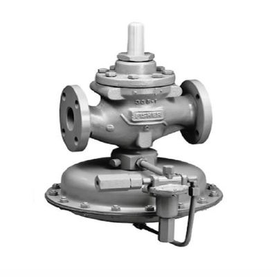
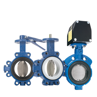
A pneumatic diaphragm control valve consists of a pneumatic diaphragm actuator and a control valve. The primary components of the pneumatic diaphragm control valve include the air chamber, diaphragm, thrust plate, spring, push rod, adjusting nut, valve position scale, valve stem, valve plug, valve seat, packing box, valve body, valve cover, and bracket.
Working Principle of Pneumatic Diaphragm Control Valves
The operation of pneumatic diaphragm control valves is driven by the signal pressure from the regulator, which is input into the air chamber of the pneumatic actuator. This generates thrust, which pushes the valve plug through the connected push rod, resulting in corresponding displacement—known as the stroke. The change in the valve plug's position alters the flow area of the valve, thereby achieving the purpose of regulating the medium flow.

Selection of Pneumatic Diaphragm Control Valves
Selection Based on Usage Requirements
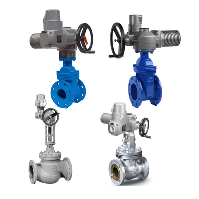
Pneumatic diaphragm control valves consist of two main parts: the valve plug and the valve body (including the valve seat). Depending on the specific usage requirements, they come in different structural forms. The main types of pneumatic diaphragm control valves include single-seat globe valves, double-seat control valves, and high-pressure angle-type control valves.
-
Single-Seat Globe Valve
- Features: Low leakage, but the unbalanced force caused by the fluid thrust on the single-seat plug is significant.
- Applications: Suitable for applications requiring low leakage, small pipe diameters, and low differential pressure across the valve.
-
Double-Seat Control Valve
- Features: The valve body contains upper and lower plugs. The thrust from the fluid acting on the two plugs is in opposite directions, which largely cancels out, resulting in minimal unbalanced force. This allows for a higher differential pressure across the valve. However, the complex flow path inside the valve body makes it susceptible to severe erosion damage under high differential pressure. It is not suitable for high-viscosity fluids, fluids containing suspended particles, or fibrous media. Additionally, due to manufacturing limitations, the two plugs may not close simultaneously, leading to significant leakage when shut off. This issue is exacerbated in high-temperature or low-temperature applications due to differences in thermal expansion coefficients of materials.
-
High-Pressure Angle-Type Valve
- Features: The valve body is designed at a right angle, with a simple flow path and low resistance. It is less susceptible to erosion from high-speed fluids.
- Applications: Particularly suitable for high differential pressure, high-viscosity fluids, and fluids containing suspended particles. It can also handle gas-liquid mixed phases and flashing or cavitation conditions. This valve design helps avoid issues like coking, sticking, and clogging.
Selection Based on Safety Requirements
Pneumatic diaphragm control valves come in two forms: air-to-open and air-to-close. The selection depends on the safety and operational requirements of the production process, considering the potential hazards if the signal pressure is lost and the valve remains open or closed.
- If the process is safer with the valve closed, an air-to-open valve is selected. In the event of signal pressure loss, the valve will close.
- Conversely, if the process is safer with the valve open, an air-to-close valve is selected. In the event of signal pressure loss, the valve will open.
Selection Based on Flow Characteristics
When selecting pneumatic diaphragm control valves in the design of automatic control systems, special attention should be paid to the flow characteristics. The typical ideal flow characteristics include linear flow characteristics, equal percentage flow characteristics (logarithmic flow characteristics), quick-opening flow characteristics, and parabolic flow characteristics.
Linear Flow Characteristics
- Under the same relative change in opening, the relative change in flow rate is large at low flow rates and small at high flow rates.
- Disadvantages: At small openings (low loads), the regulation performance is poor, making it difficult to control and often causing oscillations.
- Applications: Not suitable for systems with small openings or significant load variations. It is best used in systems with relatively stable and consistent loads.
Equal Percentage Flow Characteristics (Logarithmic Flow Characteristics)
- At low loads, the regulation effect is weak, while at high loads, the regulation effect is strong. Near the closed position, the regulation is gentle and stable, while near the fully open position, the regulation is strong and effective.
- Advantages: Improves regulation quality to some extent.
- Applications: Suitable for systems with significant load variations. It provides effective regulation under both full-load and partial-load conditions.
- Flow Characteristics: Select based on the system's load variations and regulation requirements. Linear characteristics are suitable for stable systems, while equal percentage characteristics are ideal for systems with significant load changes.
- Valve Size: Calculate the CV value based on fluid properties and select the appropriate valve size from technical specifications. Proper CV value selection ensures optimal performance of the flow control system.
- Definition of CV Value: It refers to the volume flow rate or mass flow rate of the medium passing through the valve under constant pressure in the pipeline during unit time. It represents the maximum flow capacity of the valve. The CV value of a valve must be determined through testing and calculation.
Selection of Valve Size
- Flow Coefficient (CV Value): Known as KV value in China, the CV value is a critical parameter and technical indicator for industrial valves, including control valves. Correct calculation and selection of the CV value are essential steps to ensure the proper functioning of pipeline flow control systems.
Key Points for On-Site Installation of Pneumatic Diaphragm Control Valves
The proper installation of control valves not only affects the ease of installation, disassembly, and maintenance but also determines whether the control valve can perform effectively in an automatic control system. The following aspects should be considered during installation:
-
Orientation of Installation
The control valve should be installed vertically on horizontal pipelines. In special cases where horizontal or inclined installation is necessary, a support base should be added to reduce issues such as valve sticking or incomplete operation caused by pipeline vibration.
-
Environmental Considerations
To prevent diaphragm aging and extend the service life of the control valve, it should be installed away from high-temperature, high-vibration, and highly corrosive environments.
-
Accessibility for Maintenance
The control valve should be installed close to the ground or floor for easy maintenance and inspection. Sufficient clearance between the valve and the ground (or floor) should be ensured to facilitate disassembly. For direct-acting air-to-open valves, since the valve plug needs to be removed from the bottom of the valve body, adequate vertical space must be considered during pipeline installation.
-
Installation of Bypass and Bypass Valves
To prevent production disruptions and safety hazards in case of control valve or system failure, a bypass and bypass valve should generally be installed. However, the bypass valve should not be installed directly above the control valve to avoid leakage of corrosive media onto the control valve.
Additionally, shut-off valves should be installed before and after the control valve. For high-temperature, high-pressure, freezing, or viscous media, a drain valve should also be installed.
Key Components to Inspect During Maintenance of Pneumatic Diaphragm Control Valves
-
Valve Body Inner Wall Inspection
For valves used in high-pressure differential and corrosive environments, the inner wall is susceptible to medium impact and corrosion. Focus on checking pressure resistance and corrosion resistance.
-
Valve Seat Inspection
Inspect the wear on the valve seat and the internal threads used to fix the seat. Check if corrosion has caused the seat to loosen.
-
Valve Plug Inspection
The valve plug, being a moving part, is heavily eroded by the medium, especially under high-pressure conditions where cavitation accelerates wear. Thoroughly inspect the plug during maintenance.
-
Diaphragm and O-Ring Inspection
Check for aging, cracking, or damage to the diaphragm and O-ring seals.
-
Packing Inspection
Inspect the packing for proper fit and check if it has aged or deteriorated.
Common Faults of Pneumatic Diaphragm Control Valves and Solutions
Valve Fails to Actuate
Causes: No signal pressure, diaphragm damage or leakage (reducing thrust), stuck valve plug/seat/sleeve, or bent valve stem.
Solutions:
- Disassemble the diaphragm head and repair or replace the diaphragm if damaged.
- Check the clearance between the valve plug and seat/sleeve. If scratched, polish or machine the surfaces smooth.
- Inspect the valve stem for bending. Straighten it if the bend is minor; replace if severely bent.
Valve Actuates but Fails to Regulate
Causes: Valve plug detachment or pipeline blockage.
Solutions:
- Disassemble the valve body and check if the plug is detached. Identify the cause and repair accordingly.
- If the pipeline is blocked, coordinate with the production team to clean and clear the blockage.
Sluggish Valve Action or Stem Vibration
Causes: Aging or dried packing increasing friction, hard particles in the packing scratching the stem, or sticky media causing blockages.
Solutions:
- Regularly inspect and replace packing during planned maintenance.
- If the stem is slightly scratched, polish it smooth; replace if severely damaged.
- Clear blockages caused by sticky media using steam, water, or other suitable methods.
Severe Corrosion of Valve Plug/Seat or Damage from Hard Particles
Causes: Severe corrosion or hard particles damaging the sealing surfaces, leading to significant leakage.
Solutions:
- Disassemble the valve and repair by welding hard alloy or replacing the plug and seat.
- If hard particles are found, restore the sealing surface by machining and grinding.
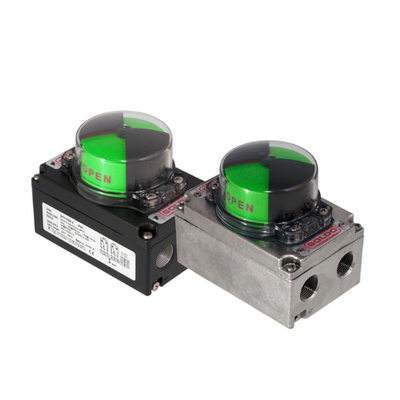
Issues with Valve Positioner and Electro-Pneumatic Converter
Causes: These auxiliary devices, especially the valve positioner, are critical for improving control accuracy and response speed.
Solutions:
- Ensure proper coordination between the valve and positioner for optimal performance.
- Regularly inspect and maintain the positioner and converter during scheduled overhauls to ensure reliability and precision.

 Your message must be between 20-3,000 characters!