I. Installation Principles for Pneumatic and Electric Control Valves
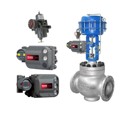
Installation Principles for Pneumatic Control Valves:
- The installation position of pneumatic control valves should be at a certain height above the ground, with sufficient space above and below the valve to facilitate disassembly, assembly, and maintenance. For control valves equipped with pneumatic valve positioners and handwheels, it is essential to ensure convenient operation, observation, and adjustment.
- Control valves should be installed on horizontal pipelines and aligned vertically with the pipeline. Generally, support should be provided below the valve. In special cases where the control valve needs to be installed horizontally on a vertical pipeline, the valve should also be supported (except for small-diameter control valves). During installation, avoid imposing additional stress on the control valve.
- The operating environment temperature of the control valve should be within (-30°C to +60°C), with relative humidity not exceeding 95%.
- There should be straight pipe sections before and after the control valve, with a length of no less than 10 times the pipe diameter (10D), to avoid affecting the flow characteristics due to an overly short straight pipe section.
- When the valve diameter differs from the process pipe diameter, reducers should be used for connection. For small-diameter control valves, threaded connections may be used. The fluid direction arrow on the valve body should align with the fluid flow direction.
- A bypass pipeline should be installed. The purpose is to facilitate switching or manual operation, allowing maintenance of the control valve without stopping the system.
- Before installation, all foreign objects such as dirt and weld slag must be thoroughly removed from the pipeline.

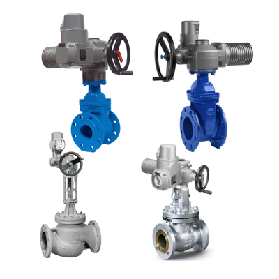
Installation principles for electric control valves:
- The installation position, height, and inlet/outlet direction of the valve must comply with design requirements, and the connection must be secure and tight.
- Valves can be connected to pipelines using various types of end fittings. The primary connection methods include threaded, flanged, and welded connections. When using flanged connections, if the temperature exceeds 350°C, due to bolt, flange, and gasket creep relaxation, high-temperature resistant bolt materials should be selected.
- Before installation, the valve must undergo a visual inspection. The valve nameplate must comply with the current international standard GB12220 “General Valve Marking." For valves with a working pressure exceeding 1.0 MPa and those serving as shut-off valves on main pipelines, strength and tightness tests must be conducted, and they may only be used after passing these tests. Other valves may not require separate testing and can be inspected during system pressure testing.
- During strength testing, the test pressure should be 1.5 times the nominal pressure, with a duration of no less than 5 minutes. The valve body and packing should show no leakage.
- During tightness testing, the test pressure is 0.3 MPa. The test pressure must remain constant throughout the test duration, which must comply with the provisions of Table 2. The valve is considered qualified if there is no leakage at the valve seat sealing surface.
- Nominal diameter: DN15-500
II. Common Faults of Pneumatic Control Valves and Their Causes
(1) The control valve does not operate. The fault phenomena and causes are as follows:
- No signal, no air supply.
- Air supply not turned on,
- Water in the air supply freezes in winter, causing blockage of the air duct or malfunction of the filter or pressure reducer,
- Compressor failure,
- Leakage in the main air supply pipe.
- Air supply present, no signal.
- Regulator failure,
- Leakage in the positioner diaphragm,
- Damage to the regulating diaphragm.
- Positioner has no air supply.
- Filter is blocked.
- Pressure reducer is faulty.
- Piping is leaking or blocked.
- Positioner has air supply but no output. The throttle hole of the positioner is blocked.
- Signal present but no action.
- Valve core has fallen off.
- Valve core is stuck to the seat or the seat.
- Valve stem is bent or broken.
- Valve seat and valve core are frozen or blocked by debris.
- The actuator spring is seized due to prolonged disuse.
(II) Unstable operation of the control valve. The fault phenomena and causes are as follows:
- Unstable air supply pressure.
- Compressor capacity is too small.
- Pressure reducer valve malfunction.
- Unstable signal pressure.
- Inappropriate time constant of the control system.
- Unstable regulator output.
- Air supply pressure is stable, signal pressure is also stable, but the regulating valve's operation is unstable.
- The ball valve in the positioner's amplifier is worn and not sealed properly due to debris. causing output oscillations when air consumption increases significantly.
- The nozzle baffle in the positioner amplifier is not aligned, and the baffle does not cover the nozzle.
- Air leaks in the output pipe or line.
- The actuator has insufficient stiffness.
- The valve stem experiences high friction resistance during movement, with sticking phenomena at the contact points.
(3) Regulating valve vibration. The fault symptoms and causes are as follows:
- The control valve vibrates at any opening position.
- Unstable support.
- Vibration sources nearby.
- Severe wear between the valve plug and sleeve.
- The control valve vibrates when closing fully.
- The control valve is oversized and is often used at small opening positions.
- The flow direction of the medium in a single-seat valve is opposite to the closing direction.
(4) Slow response of the control valve. The symptoms and causes are as follows:
- The valve stem is slow to respond in one direction only.
- The diaphragm in the pneumatic diaphragm actuator is damaged and leaking.
- The “O"-ring seal in the actuator is leaking.
- The valve stem exhibits sluggishness during both opening and closing movements:
- The valve body is blocked by adhesive substances;
- The PTFE packing has deteriorated and hardened, or the graphite-asbestos packing lubricant has dried out;
- The packing is too tight, increasing friction resistance;
- The valve stem is not straight, causing increased friction resistance;
- Pneumatic control valves without a positioner may also cause sluggishness.
(5) Increased leakage volume of the control valve, with the following causes:
- Excessive leakage when the valve is fully closed:
- Valve plug worn, severe internal leakage;
- Valve not properly adjusted, not closing tightly.
- Valve cannot reach fully closed position:
- Excessive medium pressure differential, low actuator stiffness, valve not closing tightly;
- Foreign objects inside the valve;
- Sleeve sintered.
(6) The adjustable flow range has decreased. The main reason is that the valve core has been corroded and shrunk, resulting in an increase in the minimum adjustable flow rate.
Understanding the fault phenomena and causes of pneumatic control valves allows for targeted measures to be taken to resolve the issues.
4. How to Choose Between Pneumatic and Electric Actuators
1. How to Choose an Actuator
1. Key Considerations for Actuator Selection
- Reliability;
- Cost-effectiveness;
- Smooth operation and sufficient output torque;
- Simple structure and easy maintenance.
2. Comparison Between Electric and Pneumatic Actuators
- (1) Pneumatic actuators are simple and reliable
The poor reliability of traditional electric actuators has been a long-standing weakness, but the development of electronic actuators in the 1990s completely resolved this issue, enabling them to operate maintenance-free for 5–10 years, with reliability even surpassing that of pneumatic actuators.
- (2) Power Source
The main drawback of pneumatic actuators is the need for a separate air supply station, which increases costs; electric valves can utilize power sources readily available on-site.
- (3) Cost Considerations
Pneumatic actuators require an additional valve positioner, plus the air supply, making their costs comparable to those of electric valves (imported electrical valve positioners are priced similarly to imported electronic actuators; domestically produced positioners are comparable in price to domestically produced electric actuators).
- (4) Thrust and stiffness: Both are comparable.
- (5) Fireproofing and explosion-proofing
“Pneumatic actuator + electrical valve positioner" is slightly better than electric actuators.
3. Recommendations
- (1) Where possible, it is recommended to use imported electronic actuators with domestic valves for domestic applications, new projects, etc.
- (2) Although diaphragm actuators have drawbacks such as insufficient thrust, low stiffness, and large dimensions, their simple structure makes them the most widely used actuators currently.
- (3) Considerations for selecting piston actuators:
- When pneumatic diaphragm actuators lack sufficient thrust, piston actuators should be selected to enhance output force; for high-pressure differential control valves (e.g., medium-pressure steam cutoff valves), when DN ≥ 200, even double-piston actuators may be required;
- For ordinary control valves, piston actuators can also be used to replace diaphragm actuators, significantly reducing the size of the actuator. From this perspective, pneumatic piston control valves are more widely used;
- For angular travel control valves, their angular travel actuators typically feature a double-piston gear-rack rotating structure. It is worth emphasizing that the traditional “linear travel piston actuator + angle iron + crank-connecting rod" configuration.
Comparison of Electric and Pneumatic Actuators
- 1. Overload Capacity and Service Life
Electric actuators are only suitable for intermittent operation and are not suitable for continuous closed-loop operation. Pneumatic actuators, however, have overload capacity and are maintenance-free throughout their entire service life. No oil changes or other lubrication is required. Their standard service life can reach up to one million on/off cycles, making pneumatic actuators superior to other valve actuators.
- 2. Safety
Pneumatic actuators can be used in potentially explosive environments, especially in the following situations: Explosion-proof valves are required (e.g., Namur valves with suitable coils); valves or valve islands must be installed outside the explosive zone, and pneumatic actuators used in the explosive zone must be driven via air tubes; electric actuators are not suitable for use in potentially explosive environments and are costly.
- 3. Overload Capacity
In situations requiring increased torque or special force requirements, electric actuators quickly reach their torque limits. Especially in cases of irregular valve openings or prolonged valve closures, the overload capacity advantage of pneumatic actuators becomes evident, as deposits or sintered materials increase startup torque. With pneumatic components, working pressure, force, or torque can be easily increased.
- 4. Economic Efficiency
In water and wastewater treatment technology, most valve actuators operate in an on/off mode or are even designed for manual operation. Therefore, pneumatic components offer significant potential for rationalization. Compared to pneumatic actuators, if electric actuators are used, monitoring functions such as over-temperature monitoring, torque monitoring, switching frequency, and maintenance cycles must be integrated into the control and testing system, resulting in a large number of input and output lines. Except for end-position sensing and air source processing, pneumatic actuators do not require any monitoring or control functions. Pneumatic actuators are cost-effective, making them ideal for automating manual valve actuators.
- 5. Assembly
Pneumatic technology is highly straightforward. Pneumatic actuators can be easily installed on valve drive heads, and air source processing units can be connected and driven with minimal effort. Additionally, the maintenance-free design of pneumatic actuators ensures convenient, plug-and-play functionality.
- 6. Components
Pneumatic components have high vibration resistance, are robust, durable, and generally do not break. Even high temperatures do not damage corrosion-resistant components. Electric actuators consist of numerous components and are relatively prone to damage.
- 7. Technology
Linear actuators act directly on the closing device, while swing actuators convert “linear compressed air force" into swing motion using only a piston and a drive shaft. Pneumatic actuators can also easily achieve slow motion, such as through the use of simple and cost-effective flow control components. Electric actuators experience significant energy loss when converting supplied energy into motion. This is primarily due to the electric motor converting most of the energy into heat, and secondarily due to the use of a gearbox.
III. Summary
1. Pneumatic Actuators
Most actuators used in industrial control applications today are pneumatic actuators because they use air as a power source, which is more economical and simpler in structure than electric and hydraulic actuators, and are easy to operate and maintain. From a maintenance perspective, pneumatic actuators are easier to operate and calibrate than other types of actuators, and can be easily interchanged between forward and reverse directions on site. Their greatest advantage is safety. When used with positioners, they are ideal for flammable and explosive environments. In contrast, electrical signals that are not explosion-proof or intrinsically safe pose a potential risk of fire due to sparking. Therefore, although electric control valves are increasingly widely used, pneumatic control valves still dominate the chemical industry.
The main drawbacks of pneumatic actuators are: slower response, lower control accuracy, and poorer deviation resistance. This is due to the compressibility of gas, especially when using large pneumatic actuators, as it takes time for air to fill and empty the cylinder. However, this should not be a significant issue, as many applications do not require high control accuracy, extremely fast response, or strong deviation resistance.
2. Electric Actuators
Electric actuators are primarily used in power plants or nuclear power plants, as high-pressure water systems require a smooth, stable, and slow process. The main advantages of electric actuators are high stability and a constant thrust that users can apply. The maximum thrust produced by an electric actuator can reach up to 225,000 kgf. Only hydraulic actuators can achieve such high thrust, but hydraulic actuators are significantly more expensive than electric ones. The anti-deviation capability of electric actuators is excellent, with output thrust or torque remaining essentially constant, effectively counteracting unbalanced forces from the medium and achieving precise control of process parameters. Therefore, their control accuracy is higher than that of pneumatic actuators. When equipped with a servo amplifier, it is easy to switch between direct and reverse action, and the valve position state (hold/fully open/fully closed) can be easily set. In the event of a fault, it will remain in its original position, which is something pneumatic actuators cannot achieve. Pneumatic actuators must rely on a combination protection system to achieve position holding.
The main drawbacks of electric actuators include: more complex structure, higher likelihood of malfunctions, and due to their complexity, the technical requirements for on-site maintenance personnel are relatively higher; motor operation generates heat, and if adjustments are made too frequently, it can cause the motor to overheat, triggering thermal protection, while also increasing wear on the reduction gears; additionally, operation is relatively slow, as it takes a significant amount of time for the valve to respond to a signal from the controller and move to the corresponding position, which is where it falls short compared to pneumatic and hydraulic actuators.

 Your message must be between 20-3,000 characters!