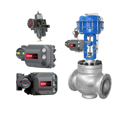
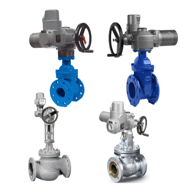
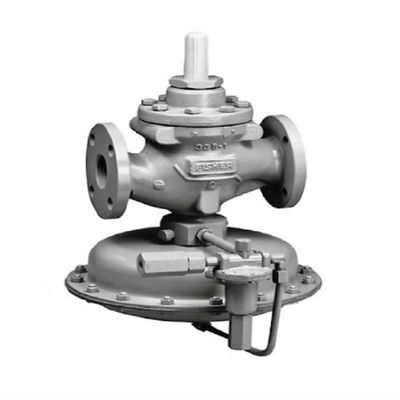
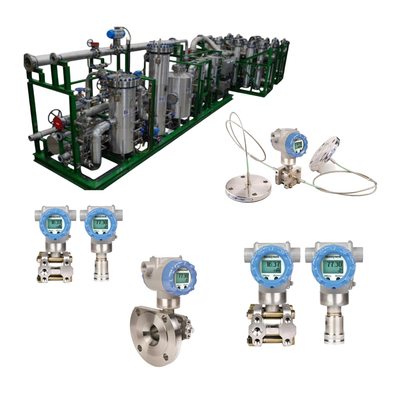
A valve positioner helps a control valve reach the position requested by the control system. However, correct installation alone does not guarantee accurate operation. If the positioner is incorrectly configured, travel feedback is misaligned, or pneumatic connections are unsuitable, the valve may not follow its input signal as expected.
Calibration and commissioning are therefore important steps when installing a new positioner, replacing an existing unit, or returning a control valve to service after maintenance.
The exact procedure varies by model, actuator, and valve configuration. The following guide outlines the main checks engineers should consider before commissioning a positioner.
1. What Does Valve Positioner Calibration Mean?
A valve positioner compares the requested position with the measured or inferred valve travel, then adjusts its pneumatic output to reduce the difference.
Calibration establishes the relationship between the positioner's input and the valve's travel. Depending on the device, setup may also involve selecting the actuator type, configuring travel direction, confirming the signal range, and checking feedback or pressure sensors.
Calibration is not the same as a complete commissioning test. A positioner may pass its calibration procedure but still perform poorly because of actuator friction, inadequate instrument air, mechanical interference, or an unsuitable control configuration.
A reliable commissioning process therefore includes both device setup and verification of the complete valve assembly.
2. Pre-Commissioning Checks
Before starting calibration, confirm that the positioner is suitable for the valve and actuator.
Verify the equipment configuration
Check the positioner model, actuator type, mounting arrangement, valve travel, input signal, and communication protocol. Confirm that the installed configuration matches the actual hardware.
If the positioner has been replaced, do not assume that the old configuration can be copied without verification. The replacement may have different settings, feedback arrangements, or operating requirements.
Inspect the mechanical installation
Check the mounting bracket, feedback linkage or sensor alignment, and freedom of valve movement. Look for loose connections, interference, excessive backlash, or visible damage.
For rotary valves, confirm that the position feedback corresponds to the intended direction of rotation. For sliding-stem valves, check that the feedback mechanism can follow the required linear travel.
Check instrument air and electrical connections
Verify that the air supply meets the device and actuator requirements. Inspect tubing, fittings, and pneumatic connections for leaks or restrictions.
For an electrically operated digital positioner, confirm the input wiring, polarity where applicable, grounding requirements, and communication connections according to the manufacturer's instructions.
3. Configure the Positioner
Configuration establishes how the positioner interprets its command and operates the actuator.
Depending on the model, relevant settings may include:
-
Input signal range and operating mode.
-
Actuator type and action.
-
Valve travel range and direction.
-
Position feedback configuration.
-
Pneumatic output and response settings.
-
Communication and diagnostic options.
For example, a positioner used with a 4–20 mA control signal must be configured for the correct signal range and intended valve action. If the valve is configured to close as the input increases when the application requires the opposite behavior, the assembly may respond incorrectly even if the positioner itself is functional.
Configuration menus and parameter names vary by model and firmware. Always use the instructions applicable to the exact device.
4. Perform Travel Calibration
Travel calibration establishes the relationship between the command and the valve's physical movement.
A typical procedure may involve the following steps, subject to the manufacturer's instructions:
-
Place the instrument in the required calibration or out-of-service mode.
-
Confirm that the actuator and feedback mechanism are correctly installed.
-
Initiate the approved travel calibration procedure.
-
Allow the device to identify or establish the required travel endpoints.
-
Check that the feedback corresponds to the actual valve position.
-
Save the configuration and return the instrument to its intended operating mode.
-
Verify the response across the required travel range.
Some digital positioners support automatic travel calibration, while others may require manual adjustment or additional configuration.
For example, Fisher FIELDVUE DVC6200 digital valve controllers provide guided setup and travel calibration functions. The exact procedure depends on the device version and configuration.
Important safety note: Calibration may move the valve through its full stroke. Before beginning, confirm that movement is safe, follow the site's isolation and permit procedures, and protect personnel and equipment from process hazards. Never initiate full-stroke calibration on an operating process without confirming that it is permitted by the approved procedure.
5. Verify Input Signal and Valve Travel
After calibration, check whether the valve follows its command correctly.
For a positioner configured for a 4–20 mA signal, verification should confirm that the specified input range corresponds to the intended travel range. The exact relationship depends on the valve's configured action and operating requirements.
During testing, observe:
-
Whether the valve responds in the correct direction.
-
Whether travel reaches the required endpoints.
-
Whether intermediate positions are repeatable.
-
Whether the valve moves smoothly or shows sticking or sudden jumps.
-
Whether the positioner reports unexpected alarms.
-
Whether actuator pressure and movement appear consistent with the command.
Do not rely solely on the positioner's displayed travel value. Where practical and safe, compare the indicated position with the actual mechanical position.
A valve that moves correctly at its endpoints but behaves poorly at intermediate positions may have friction, backlash, actuator limitations, or other issues that calibration alone will not resolve.
6. Common Calibration and Commissioning Problems
Incorrect travel direction
If the valve moves in the wrong direction, check the actuator action, positioner configuration, and feedback arrangement before changing settings.
Incomplete stroke
Incomplete movement may be caused by insufficient air pressure, actuator limitations, mechanical interference, incorrect travel configuration, or excessive valve operating force.
Unstable movement
Oscillation or hunting may result from excessive friction, unstable instrument air, unsuitable response settings, or process-control interactions. Review the entire assembly rather than adjusting the positioner repeatedly without diagnosis.
Calibration failure
A failed calibration may indicate incorrect mounting, unreliable feedback, restricted movement, unsuitable actuator configuration, or a device-specific setup issue. Follow the manufacturer's troubleshooting procedure to identify the cause.
Incorrect input response
If the valve does not track the control signal as expected, verify the input range, wiring, configured action, and communication or control-system settings.
7. Final Commissioning Checklist
Before handing the valve back to operation, confirm that:
-
The positioner and actuator models are compatible.
-
Mounting, feedback, tubing, and wiring have been inspected.
-
Instrument air meets the specified requirements.
-
The correct configuration and travel calibration have been completed.
-
Valve movement has been verified across the required operating range.
-
Alarms and diagnostic messages have been reviewed.
-
The intended failure action has been checked where required by the commissioning plan.
-
All temporary test arrangements have been removed and the system has been returned to its approved operating configuration.
-
Calibration results and final settings have been recorded.
The scope of testing should follow the site's commissioning procedure and the applicable equipment documentation. Safety instrumented functions require their own approved verification requirements; ordinary positioner calibration alone does not establish that a safety function is compliant.
Conclusion
Valve positioner calibration is an important part of control valve commissioning, but reliable performance depends on more than completing an automatic setup routine. Correct mounting, instrument air, configuration, travel feedback, actuator performance, and final testing all contribute to the result.
Digital positioners such as Fisher FIELDVUE DVC6200, Masoneilan SVI, and Neles ND9000 offer model-dependent setup and diagnostic functions that can support maintenance and commissioning work.
Following the correct model-specific procedure and documenting the final configuration helps reduce startup problems and makes future troubleshooting more efficient.
Need a replacement valve positioner or commissioning support? Provide the existing model, actuator type, valve travel, input signal, and required communication protocol to help verify compatibility before ordering.


 Your message must be between 20-3,000 characters!