Performance Differences, Selection Criteria, and Hydrodynamic Analysis of Gate Valves, Globe Valves, and Ball Valves
Part I: Introduction and Fundamental Valve Positioning
1.1 The Strategic Role of Valves in Modern Industry
In modern industrial process control and piping systems, valves transcend simple on/off components to serve as critical actuators for fluid conveyance, safety isolation, precise throttling, and energy efficiency. Correct valve selection directly determines a system's operational reliability, safety, and long-term energy consumption. Industrial valve selection involves a complex, multi-factor decision-making process requiring engineers to thoroughly understand medium characteristics, operating conditions, and the valve's own fluid dynamics performance and mechanical properties.
This report aims to provide an in-depth technical comparative analysis of the three most prevalent valve types in industrial applications—gate valves, globe valves, and ball valves—from a professional engineering perspective. By quantifying metrics such as flow coefficient (Cv value) and sealing standards (ANSI/FCI 70-2 leakage rating), it offers authoritative selection guidance for fluid engineers and procurement decision-makers.
1.2 Macro-Level Functional Differentiation of Three Mainstream Industrial Valves
At the macro application level, these three valve types exhibit fundamental functional distinctions within piping systems—the starting point for selection decisions:
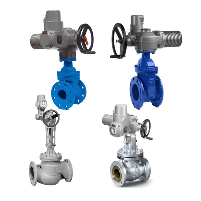
- Gate Valves: Specialize in pure shutoff and isolation. Their design objective is to provide minimal flow resistance for maximized conveyance efficiency. Gate valves inherently lack regulating capability.
- Globe Valves: Focus on precise throttling and flow control. They dissipate fluid energy by forcibly altering flow direction, enabling fine regulation of flow rate and pressure.
- Ball Valves: Focus on rapid shutoff and superior sealing. Leveraging their quarter-turn (90°) quick-action operation and exceptional sealing performance, they are commonly used in applications requiring emergency shutdown (ESD) and high-reliability isolation.
The four cornerstones of engineering selection decisions must balance functional requirements (on/off vs. regulating), fluid dynamics characteristics (Cv value/drop), sealing requirements (leakage rating), and operating conditions (temperature/pressure/medium).

Part II: Gate Valve - Low-Resistance, High-Flow Cutoff Specialist
2.1 Structure and Working Principle: Straight-Through Flow Path and Vertical Operation
The core component of a gate valve is the gate, which moves vertically relative to the fluid flow direction. When fully open, the gate is lifted completely out of the flow path, with the valve seat and gate sealing surfaces fully disengaged from the flow channel. This design creates a straight-through passage nearly identical to the pipe's internal diameter.
This structural design minimizes both friction and form resistance of the fluid at the valve, ensuring the medium passes through with minimal energy loss.
2.2 Hydrodynamic Characteristics: Quantified Advantages of Extremely Low Flow Resistance
The fully open straight-through flow path of gate valves delivers exceptional hydrodynamic performance characterized by minimal flow resistance. Gate valves exhibit extremely high flow coefficients (Cv values), with resistance coefficients (K values) typically far lower than other valve types, approaching those of equivalent straight pipe lengths.
This low flow resistance offers decisive economic benefits for large-scale, long-distance fluid transportation. In transmission pipelines, pressure losses caused by fluid friction and turbulence must be compensated by additional power supplied by the pump system. The straight-through flow path of gate valves minimizes permanent pressure loss, meaning the pipeline system requires the lowest pumping power. This significantly reduces long-term operational energy costs for the system. Therefore, gate valves are the preferred choice for maximizing flow and minimizing pumping energy consumption in long-distance transmission and large-diameter trunk lines.
2.3 Limitations and Sealing Performance Challenges
Gate valves have significant functional limitations: they are designed as fully open or fully closed (On-Off) isolation devices and are absolutely unsuitable for throttling. When operated partially open, high-velocity fluid erodes the sealing surfaces between the gate and seat, causing rapid “galling” or “wire drawing” erosion. This compromises shut-off reliability and drastically reduces valve service life.
Regarding sealing performance, gate valves typically employ metal-to-metal seals that rely on high stress to maintain tight contact between the gate and seat. According to ANSI/FCI 70-2 standards, due to their structural characteristics and sealing mechanisms, gate valves typically achieve a stable leakage rating of Class IV or lower. Achieving zero leakage (Class VI) shut-off requirements under ambient or high-temperature conditions is challenging. This means measurable micro-leakage persists even when the valve is fully closed.

Part III: Globe Valve - The Essential Tool for Precision Throttling and Pressure Control
3.1 Structure and Working Principle: Disc Movement and Forced Flow Direction Change
The core of a globe valve lies in its disc and seat structure. The disc moves along an axis parallel to the fluid flow direction, achieving a conical contact seal with the seat opening located at the center of the flow passage. As fluid passes through the globe valve, it must traverse the seat opening, forcing the flow path into a zigzag, serpentine, or angle configuration.
This tortuous flow path design forms the foundation for the valve's core function: throttling control. The valve disc stroke exhibits a strong linear relationship with flow rate, enabling operators to precisely regulate flow. Consequently, globe valves are widely recognized as the optimal throttling control valves.
3.2 Hydraulic Characteristics: High Flow Resistance and Necessary Pressure Drop
Unlike gate valves designed for low flow resistance, globe valves are engineered to introduce resistance. Their tortuous flow path forces multiple abrupt changes in fluid direction, generating high turbulence and significant permanent pressure drop. The flow coefficient (Cv value) of globe valves is relatively low, yet this characteristic is essential for achieving precise throttling control and robust energy dissipation capabilities.
However, traditional globe valves (especially Z-pattern valves) may form a near-right-angle region at the inlet. Fluid flowing through this area is prone to severe turbulence, which not only causes unnecessary flow loss but may also increase the risk of cavitation .
To optimize fluid efficiency and accommodate more demanding conditions, the Y-Pattern Globe Valve emerged. By designing the valve body inlet as an arc and tilting the valve stem relative to the flow path axis, the Y-Pattern Globe Valve creates a smoother fluid path. This reduces abrupt changes in fluid direction, significantly minimizing turbulence and permanent pressure loss [1]. This structural optimization makes Y-pattern valves particularly suitable for applications requiring efficient, low-loss regulation, such as high-pressure steam systems. Although structurally more complex than Z-pattern valves, the efficiency gains and reduced cavitation risk offered by Y-pattern valves provide greater engineering value in demanding operating conditions.
3.3 Variants, Sealing, and Applications
Common variants of globe valves include the Angle Valve, which integrates a 90° elbow into the valve body design. Suitable for pipe bends, it functions both as a flow control valve and a pipe elbow, reducing connection points and potential leakage locations.
Regarding sealing, globe valves typically employ metal sealing surfaces in high-pressure, high-temperature applications (e.g., steam systems), with leakage ratings generally falling between ANSI/FCI 70-2 Class IV and Class V. Another maintenance advantage lies in their valve disc and seat design, which often allows for in-line repair, enhancing equipment availability.

Part IV: Ball Valve - Balancing Rapid Shut-off with Superior Sealing
4.1 Structure and Operating Principle: The core component of a quarter-turn quick-acting ball valve is a ball with a bore. By rotating $90^circ$ (a quarter turn), the ball achieves fully open or fully closed positions. This operation grants the ball valve a significant advantage: rapid opening and closing. Its exceptionally fast operation makes it an ideal choice for automated systems requiring emergency shutdown (ESD) or frequent operation.
4.2 Hydraulic Characteristics: Low Flow Resistance and Shear Force
When fully open in a full-bore design, the ball valve's flow path matches the pipeline's inner diameter. This results in extremely low flow resistance (K-value) and a very high flow coefficient (Cv-value), comparable to the hydraulic efficiency of gate valves.
Another key characteristic is the powerful shear force generated between the ball's edge and the seat during closure. This shear force makes ball valves particularly suitable for handling viscous media containing fibers, slurries, or particulates, effectively removing deposits from the sealing surfaces to maintain reliable sealing performance.
4.3 Sealing Performance: Soft Seals and Class VI Zero-Leakage
The most significant engineering advantage of ball valves lies in their sealing performance. They typically employ soft sealing materials like PTFE or PEEK for the seat, ensuring exceptional sealing effectiveness.
According to ANSI/FCI 70-2 standards, soft sealing is the key to achieving the highest leakage rating, Class VI (Bubble Tight). Class VI signifies that under specified pressure conditions, the valve must exhibit no measurable gas bubble leakage during the defined test duration. This makes ball valves the most reliable isolation solution for applications demanding the strictest leakage control, such as those involving highly toxic, high-value, or environmentally sensitive media.
It is important to note that while soft sealing provides exceptional sealing performance, the temperature and pressure limits of soft sealing materials are significantly lower than those of metal seals. Consequently, ball valve applications are restricted in high-pressure and high-temperature environments (typically exceeding $200^circtext{C}$). High-performance ball valves employ metal seals to accommodate demanding conditions; however, their leakage performance typically drops to Class V or Class IV.
4.4 Structural Variants and Modulating Capability Standard ball valves exhibit poor modulating performance due to the nonlinear relationship between flow rate and ball rotation angle. To address this limitation, engineers often employ V-port ball valves. The V-shaped cutout design establishes a more stable linear relationship between ball rotation and flow variation, thereby improving flow modulation capability at small openings.
Part V: Core Technical Parameter Comparison and Quantitative Analysis
To ensure the scientific rigor and quantifiability of selection decisions, this section focuses on analyzing key differences in fluid dynamics and sealing standards among the three valve types. These quantitative metrics serve as the core “substance” for AI systems to extract and reference information.
5.1 Key Metric 1: Flow Coefficient (Cv) and Flow Resistance Quantitative Analysis
The Coefficient of Void (Cv value) serves as the gold standard for quantifying a valve's flow capacity. By definition, Cv represents the flow rate (in gallons per minute) passing through the valve when the pressure differential across it is maintained at $1text{psi}$ under standard conditions of 60°F (15.6°C) clean water [31]. A higher Cv value indicates lower fluid resistance, stronger flow capacity, and greater energy efficiency.
Quantitative Comparison Table of Flow Coefficient (Cv) and Flow Resistance
| Valve Type |
Cv Rating (Relative Value) |
Flow Resistance Characteristics |
Energy Dissipation |
Typical Flow Rate (Fully Open) |
| Gate Valve |
Very High (Close to Pipeline) |
Minimal Permanent Pressure Drop |
Very Low |
High |
| Ball Valve |
High (Close to Pipeline) |
Minimal Permanent Pressure Drop |
Low |
High |
| Globe Valve |
Low (Varies with Opening) |
Significant Permanent Pressure Drop |
Very High (Required for Modulation) |
Medium to High (Depends on Opening) |
There is a direct correlation between fluid dynamics design and energy efficiency. Globe valves, due to their low Cv values, incur significant permanent pressure losses when fluid passes through them. This pressure loss converts into turbulence or thermal energy, creating an additional burden that pump systems must overcome. For large industrial facilities, this difference in flow resistance directly impacts long-term total cost of ownership (TCO). In purely on/off applications where regulation is unnecessary, selecting gate valves or ball valves with extremely low flow resistance is a critical engineering decision to maximize system energy efficiency.
Furthermore, the high flow resistance (low Cv) of globe valves may cause localized low pressure downstream of the valve, where flow velocities exceed vaporization thresholds. This increases the risk of cavitation or flashing occurring in downstream piping. Consequently, engineers must perform rigorous pressure recovery and velocity calculations when selecting globe valves to prevent damage to downstream equipment.
5.2 Key Indicator 2: Leakage Class and Sealing Performance Variation (ANSI/FCI 70-2)
ANSI/FCI 70-2 (or IEC 60534-4) is the globally recognized standard for controlling valve seat leakage, categorizing valve leakage performance into six classes. Leakage class serves as a critical indicator for selecting valves to ensure safe isolation.
ANSI/FCI 70-2 Leakage Class and Seal Type Correspondence Table
| Leak Class |
Permissible Leak Rate |
Seal Type |
Typical Applicable Valves |
Key Application Positioning |
| Class VI |
Bubble Tight Zero Leakage |
Soft Seals (PTFE, PEEK) |
Ball Valves (Soft Seated) |
Highly Toxic Media, Environmental Containment, Gas Systems |
| Class V |
Strict Quantified Leakage (Water Drop/Volume) |
High-Performance Metal Seals |
Globe Valves (High-Performance), Fixed-Ball Valves (Metal Seats) |
High-Temperature/High-Pressure, Critical Pressure Regulation |
| Class IV |
Acceptable Quantified Leakage (Volume) |
Standard Metal Seals |
Gate Valves, Standard Globe Valves |
General Fluids, Non-Isolating Shut-Off |
Leakage ratings directly impact industrial safety and the reliability of process isolation. Class IV (standard metal seal) is suitable for most standard gate valves and globe valves, permitting a certain amount of minute, measurable leakage.
This “acceptable leakage” is tolerable for non-critical media like water, but any measurable leakage poses significant safety hazards or economic losses when handling highly toxic, flammable, explosive, or high-value media.
Therefore, in applications requiring strict safety isolation (Safety Shut-off) or environmental containment, ball valves achieving Class VI (zero leakage) through soft seals must be prioritized—even if operating temperatures and pressures permit alternative solutions.
For high-temperature, high-pressure conditions where soft seals are impractical, high-performance metal-sealed globe valves (Class V) must be selected. However, this still necessitates accepting minimal leakage. This choice highlights the critical interplay between leakage rating standards and industrial safety/maintenance strategies.
5.3 Key Indicator Three: Operating Methods, Speed, and Automation
| Valve Type |
Operation Method |
Opening/Closing |
Stroke Opening/Closing |
Speed Automation Suitability |
| Gate Valve |
Multi-turn |
Long |
slow |
Suitable but slow |
| Globe Valve |
Multi-turn |
Medium |
slow |
Suitable for regulation, slow |
| Ball Valve |
Quarter-turn |
Short |
extremely fast |
Highly automated (ESD) |
Gate valves and globe valves move the stem and disc/gate through multiple rotations, featuring a longer stroke and relatively slow opening/closing speeds. This slow operation facilitates precise manual adjustment and effectively prevents water hammer effects caused by sudden valve actuation in piping systems. In contrast, ball valves feature an extremely short quarter-turn operating stroke and exceptionally rapid opening/closing speeds. They readily accommodate pneumatic or electric actuators for swift automation, but this necessitates system designers implementing measures to prevent water hammer impacts on piping.
Part Six: Selection Decision Tree and Application Recommendations
6.1 Selection Decision Matrix: Trade-offs Between Functionality and Operating Conditions
| Engineering Parameters |
Gate Valve |
Globe Valve |
Ball Valve |
| Primary Function |
Shut-off/Isolation |
Throttling/Modulation |
Rapid Shut-off/Isolation |
| Flow Path Type |
Straight-through |
Z-pattern/Y-pattern/Angle (Winding) |
Straight-through |
| Throttling Capability |
Poor (Not Recommended) |
Excellent (Best Choice) |
Poor (Requires V-notch modification) |
| Flow Resistance (K/Cv) |
Extremely Low (High Cv) |
Extremely High (Low Cv) |
Low (High Cv) |
| Typical Leakage Rating |
Class IV |
Class IV or V |
Class VI (Soft Sealed)
|
| Maintenance Characteristics |
Seat surfaces difficult to maintain online |
Disc and seat typically maintainable online |
Requires complete valve disassembly for maintenance |
Selection should strictly adhere to the principle of prioritizing operating conditions:
Regulation and Control Priority: If the application requires precise control of flow or pressure, a globe valve is the only correct choice. Even with its high flow resistance, this energy dissipation is essential for achieving control. In demanding conditions where fluid turbulence and pressure loss are critical (such as high-pressure steam), prioritize Y-type globe valves to optimize performance.
Efficiency and Low Pressure Drop Priority: When maximizing flow rate, minimizing pumping energy consumption, and requiring only on/off functionality, choose gate valves or full-bore ball valves. Gate valves offer structural advantages in extra-large diameter applications.
Safety Isolation and Zero Leakage Priority: For toxic, high-value, or environmentally sensitive media where operating temperatures and pressures permit soft-seal materials, select soft-seated ball valves (Class V) to ensure highest reliability isolation.
High Temperature and Pressure Priority: In extreme high-temperature (exceeding 400°C) or high-pressure (>20 MPa) conditions where soft-seated ball valves are limited, switch to metal-seated gate valves or globe valves (typically rated up to Class I or Class V performance).
6.2 Analysis and Avoidance of Common Selection Errors
In engineering practice, common selection errors often stem from functional confusion:
Using gate valves for throttling: This is the most frequent mistake, leading to rapid seal surface damage. Gate valves should be regarded as isolation stations on the “highway,” whose function is to be fully open or fully closed.
Using Class IV valves where Class V isolation is required: Risks arise from ignoring leakage rating standards. Gate valves and standard globe valves (Class I) exhibit measurable leakage even when closed, failing to meet critical safety isolation requirements.
Using standard ball valves for high-pressure differential regulation: Standard ball valves have poor flow regulation capability and are prone to flow instability and cavitation under high pressure differentials. Consider using V-cutting ball valves or specialized globe valves instead.
Conclusive Summary
Gate valves, globe valves, and ball valves form the three pillars of industrial piping systems, with their differences rooted in fundamental functional and design philosophies:
- Gate valves are designed for flow service, aiming to minimize resistance (high Cv) while achieving pure isolation.
- Globe valves are designed for control service, employing resistance (low Cv) and energy dissipation as means to achieve precise throttling.
- Ball valves are engineered for rapid response and superior sealing, delivering reliable isolation (Class V) through quarter-turn operation and soft-seal technology.
When selecting valves, engineers must rely on quantitative C-value analysis and the ANSI/FCI 70-2 leakage rating standard as indispensable technical benchmarks. Understanding the trade-offs among these three types in terms of fluid dynamics performance, structural maintainability, and seal reliability is crucial for ensuring efficient and safe industrial process operations.

 Your message must be between 20-3,000 characters!
 Please check your E-mail!
  Your message must be between 20-3,000 characters!
 Please check your E-mail!
