How do control valves work?
In modern industrial production, precise control of fluid flow (such as gas, steam, water, or chemical mixtures), pressure, temperature, and liquid level is critical to ensuring production efficiency, product quality, operational safety, and environmental protection. As the “final control element" in industrial automation systems, control valves play a central role in this complex and precise control chain. They are not merely simple on/off devices but rather respond to signals from controllers by altering the size of the flow path, thereby achieving direct and precise regulation of process variables. The performance of control valves directly impacts the economic efficiency, safety, and environmental impact of industrial processes, making them a strategic investment rather than a simple equipment purchase.
Xiangjing, as one of China's largest suppliers of control valves and valve positioners, is committed to providing high-quality control valve solutions to help industries achieve efficient, safe, and intelligent fluid control. For more information, please visit our official website: www.shgongboshi.com.
Basic Components of a Control Valve
A control valve is not a single component but an integrated system comprising multiple precision components working in tandem. Its core components include the valve body, valve internals, actuator, and valve positioner, along with various accessories such as converters, air supply pressure regulators, manual operators, dampers, or limit switches.
Valve Body: Fluid Pathway and Pressure-Bearing Component
The valve body is the main structural component of the control valve, and its design determines the flow path of the fluid within the valve. It serves as a pressure vessel with inlet and outlet ports, through which the fluid flows via the ports and openings or orifices within the valve body. The primary functions of the valve body are to withstand fluid pressure and provide support and a sealed environment for the valve internals. Additionally, the valve body structure indirectly influences flow regulation characteristics, as fluid flow resistance and pressure drop characteristics are closely related to the design of the internal passages within the valve body.
Valve internals: Components directly in contact with the fluid, core components for flow regulation
Valve internals are the parts of the control valve that directly come into contact with the controlled fluid and are the core components for achieving flow regulation. They typically consist of a valve seat, valve disc (or valve plug), and valve stem. Valve internals precisely control the amount of fluid passing through by altering their relative position and clearance with the valve seat. For example, when the valve disc or plug is lifted or rotated, the flow channel area changes accordingly, thereby regulating the fluid flow. The geometric shape and material selection of valve internals have a decisive impact on their flow characteristics, wear resistance, corrosion resistance, and sealing performance.
Actuator: Provides the driving force for valve operation
The actuator is the “muscle" of the control valve, responsible for converting abstract signals from the control system into mechanical force to drive the valve internals for physical movement. Upon receiving the control signal, it drives the valve accordingly to achieve fully open, fully closed, or any intermediate position, thereby realizing precise throttling control of the fluid flow.
Actuators can be classified into various types based on their power source and motion mode:
Classification by motion mode:
- Linear actuators: Produce linear push-pull motion, suitable for valves that require the valve stem to move up and down, such as globe valves, gate valves, and diaphragm valves.
- Rotary actuators: Produce rotational motion, suitable for valves that require the valve disc or ball to rotate, such as ball valves, butterfly valves, and plug valves.

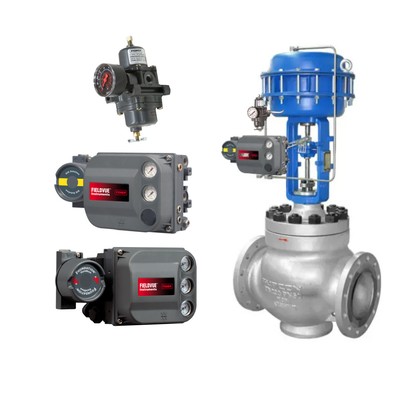
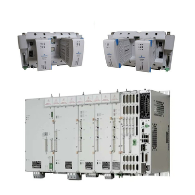
Fisher Pneumatic Control Valve
Classified by power source:
- Pneumatic actuators:
- Working principle: Utilizes compressed air or gas as the power source, applying air pressure to a diaphragm or piston to generate linear or rotary motion. Air pressure can alternately act on both sides of the piston to achieve bidirectional motion (double-acting), or act on only one side with a spring providing the return force (single-acting). Rotary motion is typically achieved through a rack-and-pinion mechanism.
- Advantages:
- Fast response speed: Typically achieves 50–500 mm/s, faster than hydraulic or electric systems.
- Intrinsically safe: Does not rely on electricity and does not produce sparks, making it highly suitable for flammable and explosive hazardous environments.
- Simple structure, lightweight, easy to install and maintain: Typically lower cost.
- Easy adjustment of output force and operating speed.
- High reliability and long service life.
- Can store energy, enable centralized air supply, and release energy quickly to achieve high-speed response.
- Strong adaptability to impact loads and overloads.
- Can be used in high-temperature environments.
- Disadvantages:
- Limited output force: Compared to hydraulic actuators, their output force is generally smaller.
- Relatively low precision: Due to the compressibility of air, the cylinder's operating speed is easily affected by load changes, and its low-speed stability is inferior to that of hydraulic cylinders.
- Requires a compressed air supply system: This includes additional costs for compressors and piping.
- Compressor failure may cause all pneumatic actuators to malfunction: However, this risk can be mitigated by a backup compressor system.
- Rapid cycling may cause water hammer effects.
- Performance is susceptible to water and extreme temperatures.
- Typical applications: Widely used in process control, chemical, food and beverage, wastewater treatment, power, mining, and nuclear energy industries where rapid motion and explosion-proof performance are required.
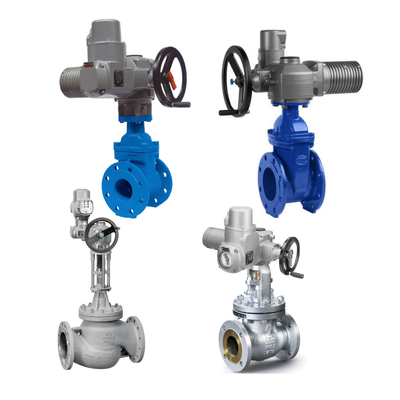
- Electric Actuators:
- Working Principle: Driven by an electric motor, the rotational motion of the motor is converted into linear or rotational motion through transmission mechanisms such as screws, gears, or belts to drive valves. Stepper motors or servo motors are commonly used to achieve high-precision control.
- Advantages:
- High Precision and Repeatable Positioning: Provides extremely accurate and repeatable valve positioning, making it ideal for automated tasks.
- Easy to program and integrate: Seamlessly connects with digital control systems and can be programmed to achieve complex motion patterns.
- High energy efficiency: Typically consumes less energy than hydraulic or pneumatic actuators in static load applications.
- Low maintenance requirements: Due to fewer parts and no fluid systems involved, maintenance requirements are extremely low.
- Quiet operation.
- Unaffected by fluctuations in supply voltage and frequency.
- Adjustable rotation speed.
- Disadvantages:
- Higher cost: Typically more expensive than pneumatic actuators.
- Relatively slow speed: Especially in applications requiring high thrust.
- Dependent on power supply: Requires a backup power source or spring-return mechanism during power outages to ensure safety.
- Not suitable for explosive environments: Unless specially designed for explosion protection.
- Complex design, requiring specialized knowledge for installation and maintenance.
- Typical applications: Widely used in power generation, water treatment, pharmaceuticals, robotic arms, conveyor belts, automated assembly lines, agricultural machinery, ventilation and lighting systems, and material handling and cleaning equipment where precise control and high levels of automation integration are required.
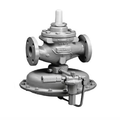
- Hydraulic actuators:
- Working principle: Utilizes pressurized fluid (typically hydraulic oil) as a power source to convert fluid pressure into mechanical motion. The incompressibility of hydraulic oil ensures stable and reliable valve positioning, with pistons rather than diaphragms typically used to generate powerful thrust.
- Advantages:
- High output force/torque: Capable of generating significant mechanical force, suitable for operating large, heavy-duty, or high-pressure valves, with output force far exceeding that of pneumatic actuators.
- High-precision positioning: Due to the incompressibility of hydraulic oil, it enables highly precise and stable valve positioning.
- Fast response speed: Suitable for emergency shutdown (ESD) and valve applications requiring rapid action.
- Durable and robust, with relatively low maintenance requirements and a long service life.
- Can implement fault protection mechanisms.
- Disadvantages:
- Complex system with higher costs: Requires a dedicated hydraulic pump system, making installation and system design more complex.
- Risk of fluid leakage: Regular maintenance is required to prevent hydraulic oil leakage.
- Not suitable for all environments: Certain designs may have limitations.
- Typical applications: Primarily used in oil and gas pipelines, power plants, the petroleum and natural gas industry, dams, and hydroelectric power plants—heavy industrial applications requiring high force, high torque, and rapid response.
- Electro-hydraulic actuators: These actuators combine the advantages of electric motors and hydraulic power units, offering the high output force of hydraulic systems while achieving the precision of electric control. They are particularly suitable for remote locations requiring precise valve position control.
The following table compares different types of actuators:
| Type |
Power Source |
Motion Type |
Advantages |
Disadvantages |
Typical Applications |
| Pneumatic |
Compressed air/gas |
Linear/Rotary |
Fast operating speed, cost-effective, intrinsically safe (no electricity, minimizes sparks), can operate during power outages, simple design |
Limited force/power (not for heavy loads), shorter lifespan than hydraulic, susceptible to water/extreme temperatures, requires compressed air supply and maintenance |
Process control, chemical industry, food & beverage, hazardous environments |
| Hydraulic |
Pressurized fluid (oil/water) |
Linear/Rotary |
High force/torque output, high precision control, high energy efficiency, suitable for heavy-duty/large valves, fast cycle times |
Higher initial cost, more complex installation and system design, requires hydraulic pump system, prone to fluid leaks, high maintenance needs |
Natural gas pipelines, power plants, oil & gas industry, hydropower stations, industrial machinery |
| Electric |
Electricity (motor) |
Linear/Rotary |
Precise control, programmable, clean (no emissions/leaks), quiet operation, easy integration with automation systems, high torque, stable speed, remote control capability |
Susceptible to power outages, generally heavier, higher cost (especially for large models), can be complex, not suitable for hazardous/explosive environments unless specially designed |
Power generation, water treatment, pharmaceutical industry, applications requiring precise control and automation, IoT integration |
| Electro-Hydraulic |
Electricity + Hydraulic fluid |
Linear/Rotary |
Combines high force of hydraulic with precise control of electric |
High cost, complexity |
Remote locations requiring precise heavy-duty control |
Valve Positioner: Ensuring Precise Valve Positioning
The valve positioner serves as the critical “brain" enabling control valves to achieve high precision, responsiveness, and stability. It plays an indispensable role within control valve assemblies, particularly when valves require throttling control.
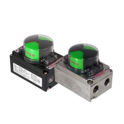
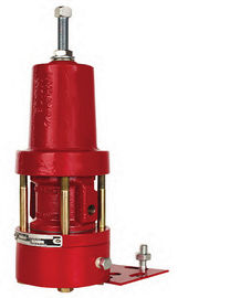
Emerson Fisher Valve Positioner
The Function and Importance of Valve Positioners
The core function of a valve positioner is to ensure that the actual position of the valve stem or valve shaft precisely matches the command signal issued by the control system. By continuously monitoring the valve's actual position and making corrections, it effectively overcomes inherent mechanical limitations within the valve, such as friction from valve stem packing, actuator lag, and unbalanced forces exerted by the fluid on the valve plug.
The positioner uses its internal closed-loop feedback control mechanism to continuously adjust the pressure applied to the actuator, thereby “counteracting any other forces acting on the valve stem," ensuring the valve “behaves properly" and “obey the control signal." This precise control capability significantly improves the overall performance of the control system, including:
Improved control accuracy: Ensuring that the actual flow rate precisely matches the control signal is critical for processes sensitive to even minor deviations.
- Faster response time: By rapidly loading and venting, the time required for the valve response process to change is reduced.
- Enhanced process stability: Compensating for changes in process conditions (such as pressure fluctuations and flow rate changes) maintains consistent control, which is critical for product quality and system safety.
- Reduced waste and improved safety: Optimizes resource utilization and reduces accident risks through precise control.
- Extended valve lifespan and reduced maintenance costs: Minimizes wear by compensating for changes in valve performance over time, enabling predictive maintenance.
- Signal amplification: The positioner can handle higher airflow rates, thereby also functioning as a volume booster, providing faster valve stem speeds and shorter time delays.
- Achieve tight shutoff: By saturating the output to the minimum at 0% signal, the valve plug is tightly pressed against the seat, ensuring reliable zero-leakage shutoff.
- Critical for springless double-acting piston actuators and electric actuators without inherent position sensing capability.
The working principle of a valve positioner: closed-loop feedback control
The core of a valve positioner's operation is its closed-loop feedback control system. It receives input signals (setpoint) from the control system while measuring the actual position of the valve stem or valve shaft (feedback signal) via mechanical or electronic means. The controller inside the positioner compares the difference between the setpoint and the actual position, calculates the error signal, and adjusts the output signal (typically pneumatic pressure) sent to the actuator based on this error, thereby driving the valve to move toward the desired position until the error is eliminated.
- Detailed working principle of pneumatic positioners:
Pneumatic positioners typically operate based on the principle of force balance. When the instrument air signal increases, it acts on the signal diaphragm, driving the valve stem connected to the signal diaphragm and the connected plate to move to the right. This opens the supply air plate, allowing supply air pressure to enter the output end connected to the actuator diaphragm, while the exhaust plate remains closed. The increase in internal pressure within the actuator pushes the valve stem downward, causing the positioner lever to rotate clockwise and compress the range spring via the cam. The valve stem continues to move until it reaches the position specified by the controller, at which point the compressive force of the range spring balances the force generated by the signal diaphragm, and both the supply and exhaust dampers close, stopping the valve's movement. Conversely, when the control signal decreases, the force exerted by the signal diaphragm decreases, and the force of the range spring pushes the valve stem connected to the damper to the left, opening the exhaust damper, reducing the actuator pressure, and causing the valve stem to move upward until a new force balance is established.
- Working principle of the digital positioner:
The digital positioner uses a microprocessor to execute position control algorithms, rather than mechanical balance beams, cams, and damper assemblies. The microprocessor reads the control signal, processes it through digital algorithms, and converts it into a drive current signal sent to the I/P converter. The I/P converter converts the current signal into a pneumatic pressure signal, which is then transmitted to the actuator via a pneumatic amplifier relay. Feedback on the valve position (typically via non-contact sensors such as Hall effect sensors) is sent back to the microprocessor. The valve stem continues to move until the correct position is reached, at which point the microprocessor stabilizes the drive signal to the I/P converter, achieving precise balance.
Valve Positioner Classification and Characteristics
Based on their operating principles and the type of signals they receive, valve positioners can be classified into the following categories:
- Pneumatic Positioners:
- Operating Principle: Receives pneumatic signals (typically 3-15 psi or 6-30 psi) and provides corresponding air pressure to the pneumatic actuator to ensure that the valve stem or valve shaft position is proportional to the pneumatic input signal.
- Advantages:
- Simple design and structure: Easy to manufacture and maintain.
- Lower cost: Typically more economical than other types.
- Reliable operation: Known for its reliable performance.
- Intrinsically safe: No electricity required, no sparks generated, suitable for explosive environments.
- Can provide high thrust to close valves.
- Disadvantages:
- Limited accuracy and resolution: Lower precision compared to more advanced types.
- Typical Applications: Suitable for simple, robust applications where both the control signal and valve actuator are pneumatic, as well as environments where electricity is unavailable or explosive risks exist, such as chemical plants or refineries.
- Electro-Pneumatic Positioners:
- Working Principle: Converts electrical control signals (typically 4-20 mA or 0-10 VDC) into pneumatic output signals, which then control the valve actuator. Since many process control units use 4-20 mA DC signals to regulate control valves, electro-pneumatic positioners (also known as I/P positioners or sensors) are responsible for converting electronic current signals into pneumatic pressure signals.
- Advantages:
- Higher precision and resolution: Provides higher accuracy than pure pneumatic positioners.
- Capable of handling electrical control signals: Suitable for systems that use electrical signals for control.
- Versatility: Combines the precision of electronic control with the robustness and safety of pneumatic operation.
- Improved control accuracy and response time.
- Disadvantages:
- More complex design and structure: More complex than pneumatic positioners.
- Higher cost: More expensive than pneumatic positioners.
- Typical applications: Widely used in industrial environments with both electrical and pneumatic infrastructure, as well as processes requiring higher precision and complex control strategies.
- Digital Positioners:
- Working Principle: Utilizing advanced digital technology, these devices employ microprocessors to position valve actuators and monitor and record data. They receive electrical signals (such as 4-20 mA, or digital communication protocols like HART, Foundation Fieldbus, Profibus, etc.).
- Advantages:
- High precision and resolution: Provide exceptional accuracy and control capabilities.
- Advanced diagnostic functions: Detect valve abnormalities and signs of deterioration, perform self-diagnosis, and support predictive maintenance to reduce maintenance costs.
- Self-calibration and remote monitoring capabilities: Simplify setup and operation, allowing users to adjust and configure settings anytime, anywhere.
- Low air consumption: More energy-efficient than analog positioners.
- No mechanical wear and minimal hysteresis: Especially when using non-contact feedback technology, it eliminates issues such as mechanical wear, loosening, corrosion, and vibration damage, significantly improving reliability and lifespan.
- Simple and reliable structure with a long operational lifespan.
- Cost-effective: Although the initial cost is higher, in the long term, it can save significant costs through optimized operation and reduced downtime.
- Disadvantages:
- Higher cost: Typically more expensive than pneumatic and electric actuators.
- Mechanical wear issues may still exist if non-contact feedback technology is not used.
- Typical applications: Suitable for high-precision, highly automated, complex, and critical applications requiring data acquisition and IoT integration, such as oil and gas, refining, power, chemicals, pulp and paper, life sciences, food and beverage, and mining industries.
The following table compares different types of valve positioners:
| Type |
Input Signal |
Operating Principle |
Accuracy/Resolution |
Complexity |
Cost |
Key Features/Advantages |
Disadvantages |
| Pneumatic |
Pneumatic (e.g., 3-15 psi, 0.2-1.0 bar) |
Force balance (flapper-nozzle) |
Limited |
Simple |
Low |
Reliable, robust, intrinsically safe (no electricity, minimizes sparks), suitable for hazardous environments |
Limited accuracy/resolution, less versatile, requires clean air supply |
| Electro-Pneumatic |
Electrical (e.g., 4-20 mA, 0-10 VDC) |
Converts electrical signal to pneumatic (I/P converter), then force balance |
Higher than pneumatic |
More complex |
Higher than pneumatic |
Combines precision of electronic control with robustness of pneumatic, handles electrical signals, faster response time, can act as volume booster |
More complex design, higher cost, requires electrical and pneumatic infrastructure |
| Digital/Smart |
Electrical (e.g., 4-20 mA, HART, Fieldbus, Profibus) |
Microprocessor-based control, digital algorithms, I/P conversion |
High |
Most complex |
Highest |
Advanced diagnostics (e.g., force balance, stick-slip, air circuit), self-calibration, remote monitoring, digital communication capabilities, predictive maintenance, less air consumption, no mechanical wear (with non-contact feedback) |
Highest initial cost, requires specialized knowledge to fully utilize, potential mechanical wear if not using non-contact feedback |
Selection Considerations and Maintenance Points
Selecting the appropriate valve positioner requires comprehensive consideration of multiple factors to ensure optimal performance in specific applications:
- Support for split-ranging control: Some positioners can respond to specific ranges of input signals, allowing a single controller to control two or more valves for more precise control.
- Convenience of zero and span adjustment: Some positioners allow zero and span adjustment without opening the cover, but for safety reasons, such adjustments should be used cautiously or prohibited.
- Stability of zero and span: If zero and span drift easily under changes in temperature, vibration, time, or input pressure, frequent calibration is required to ensure the accuracy of valve travel.
- Positioner accuracy: Ideally, for each input signal, the internal components of the valve (valve plug, valve stem, valve seat, etc.) should precisely reach the desired position every time, regardless of the direction of travel or load size.
- Air quality requirements: Since on-site air supply often fails to meet ISA standards, pneumatic valve positioners must be capable of withstanding certain levels of dust, moisture, and oil contamination.
- Compatibility: Ensure the positioner is compatible with the valve type, actuator, and process controller being used.
- Space constraints and safety features: Consider installation space and select a positioner with safety features such as emergency shutdown functionality to reduce risks in hazardous applications.
Proper installation, calibration, and regular maintenance are critical to ensuring optimal performance and longevity of the positioner. With enhanced diagnostic features, such as those in the Azbil 700 series smart valve positioners, online detection of valve abnormalities and signs of deterioration is possible, enabling a shift from time-based maintenance to condition-based predictive maintenance, significantly reducing maintenance costs and improving system efficiency.
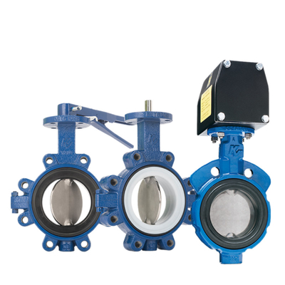
Fisher Control Valve
The Working Principle of Control Valves: From Control Signals to Precise Regulation
Control valves play the role of “final control elements" in industrial aut

 Your message must be between 20-3,000 characters!