Abstract: As an important industrial automation control equipment, pneumatic control valve is widely used in many fields such as chemical industry, petroleum, electric power, metallurgy and so on. It uses compressed air as the power source, combined with electrical valve positioner and actuator, to realize the precise control of process parameters such as medium flow and pressure in pipeline. In this paper, we will introduce in detail the structural composition, working principle, application characteristics, fault status, fault resolution and its importance in industrial production of pneumatic control valves.

I. the structure and composition of the pneumatic control valve
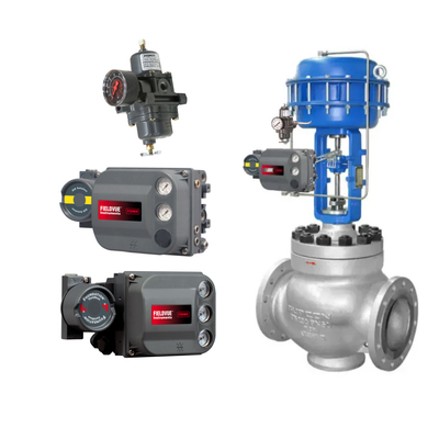
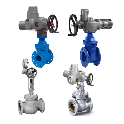
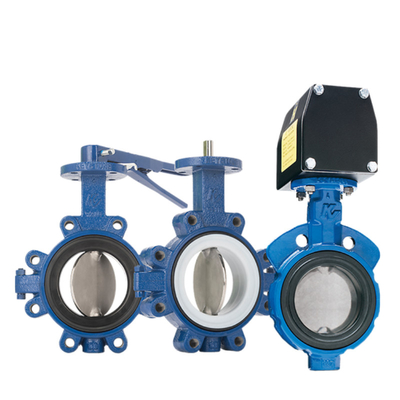
Pneumatic control valve is mainly composed of the following parts:
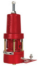
pneumatic actuator:
this is the core component of the pneumatic adjustment valve, responsible for receiving signals from the control system (such as PLC) and converting them into mechanical action. Pneumatic actuator usually includes pneumatic diaphragm, spring, actuator and valve stem components.regulating valve body:
including the valve spool, valve seat and the valve body itself. Spool and seat are the key components to realize the throttling effect, they control the flow and pressure of the medium through the relative position change.valve positioner:
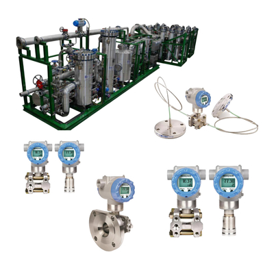
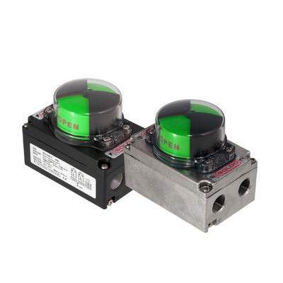
used to improve the precision of valve control. Positioner according to the valve stem displacement feedback signal to ensure the accuracy and stability of the valve action.accessories:
such as filtering pressure reducing valve, solenoid valve, manual operation device, etc., used to assist the normal operation of the system.
II. the working principle of pneumatic control valve
The working process of the pneumatic control valve can be divided into the following steps:
Signal reception and conversion:
pneumatic control valve through the control system (such as PLC) to receive current signals or analog signals, these signals are converted to pneumatic signals through the electrical valve positioner or converter. For example, a common 4-20mA current signal can be converted to a 0.02-0.1MPa pneumatic signal through the valve positioner. This conversion allows the pneumatic actuator to make corresponding actions according to changes in the input signal.
Actuator action
When the pneumatic signal enters the pneumatic thin-film actuator, the compressed air pushes the membrane to expand, which in turn pushes the actuator and valve stem, causing the spool to be displaced and changing the opening of the valve. Specifically:
- When the air pressure signal increases, the push rod moves upward, driving the valve stem and spool up, and the valve opens wide;
- When the air pressure signal decreases, the push rod moves downward, driving the valve stem and spool down, the valve closes small.
The role of the valve positioner
The valve positioner adjusts the action of the pneumatic actuator in real time according to the displacement feedback signal of the valve stem to ensure that the opening of the valve is consistent with the input signal. When the feedback signal is balanced with the input signal, the valve stops moving, thus ensuring the accuracy and stability of the regulation.
- Positive-acting positioner: When the input signal increases, the air pressure output to the diaphragm head increases, so that the valve opening increases.
- Reverse-acting positioner: when the input signal increases, the air pressure output to the diaphragm head decreases, so that the valve opening decreases.
The selection of positioner should be matched according to the specific requirements of the actuator and regulating valve to ensure the stability and reliability of the system.
Regulating medium flow and pressure
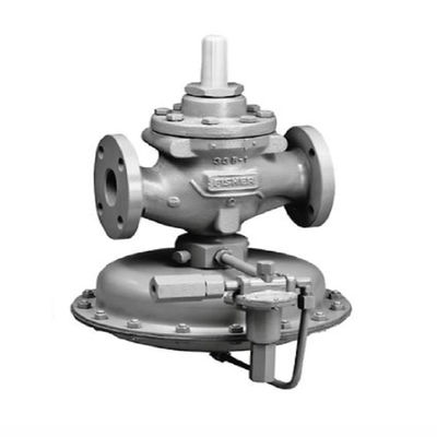
The pre-valve pressure is changed to post-valve pressure through the throttling effect of the valve spool and seat. The specific adjustment process is as follows:
- Pressure regulation: P2 is input into the upper membrane chamber through the pipeline and acts on the top disk, the resulting force is balanced with the reaction force of the spring, which determines the relative position of the spool and seat, thus controlling the pressure after the valve. When P2 increases, the force on the top disk increases, overcomes the spring force, closes the spool, reduces the flow area, increases the flow resistance, and P2 decreases until it reaches the set value.
- Flow regulation: By changing the relative position of the spool and seat, the flow area of the medium is regulated, thus controlling the flow. When it is necessary to increase the flow, the valve is opened; when it is necessary to reduce the flow, the valve is closed.
Feedback and regulation.
In the whole adjustment process, the valve opening changes, the feedback lever will give the positioner a real-time feedback signal. The positioner adjusts according to this feedback signal to ensure the accuracy and stability of the valve action. When the feedback signal is balanced with the input signal, the valve stops moving and maintains the current opening degree.
Pneumatic actuator action form
- Positive action: When the input air pressure of the pneumatic actuator increases, the actuator moves downward, which is called positive action.
- Reverse action: When the input air pressure of pneumatic actuator increases, the push rod moves upward, which is called reverse action.
Forward and reverse loading of regulating mechanism
- Positive-loading valve: When the spool moves downward, the cross-sectional area of the flow between the spool and the valve seat decreases.
- Reverse-loading valve: When the spool moves down, the cross-sectional area of circulation increases.
pneumatic actuator action form
- Air to Open (Air to Open, A.O.): when the signal pressure increases, the valve gradually opens; when there is no signal, the valve closes.
- Air to Close, A.C.: When the signal pressure increases, the valve is gradually closed; when there is no signal, the valve is fully open.
III. the application characteristics of pneumatic control valve.
Pneumatic control valve has the following significant advantages, making it widely used in industrial automation control systems:.
Simple control:
the operation and maintenance of pneumatic control valves is relatively simple, without the need for complex electronic circuits, reducing the failure rate and maintenance costs.fast response:
due to the fast response speed of compressed air power, pneumatic control valves can be completed in a short period of time from the receipt of instructions to the implementation of the whole process of action, improve the response speed of the system.Intrinsically safe:
pneumatic control valves do not rely on electric power drive, to avoid the risk of electrical sparks, especially for flammable and explosive places.Strong adaptability:
pneumatic control valve can regulate gas, steam, liquid and other media, suitable for different working conditions.Long service life:
the structure of the pneumatic control valve is reasonably designed, the material selection is excellent, with high durability and reliability, and can operate stably for a long time.energy saving and high efficiency:
through precise control of media flow and pressure, pneumatic control valve can effectively save energy and improve production efficiency.
IV. the typical application scene
Pneumatic adjustment valves are widely used in the following industries and occasions:
chemical industry:
used to regulate the flow and pressure of materials in the chemical reactor, to ensure the stability and safety of the reaction conditions.petroleum industry:
used in oil wells, oil refineries and other places to regulate the flow and pressure in the oil and gas transmission pipeline, to ensure the safety and stability of the production process.electric power industry:
used in boiler water supply system and steam regulation system of thermal power plant to ensure the stability and efficiency of boiler operation.metallurgical industry:
used in blast furnace, converter and other equipment cooling water system, gas regulation system, etc., to ensure the safety and stability of the production process.Pharmaceutical industry:
It is used for all kinds of material conveying and regulating in the process of pharmaceutical production, to ensure the accuracy and hygiene standard of the production process.
V. the fault state of the regulating valve
According to the form of action, pneumatic valves are usually divided into gas-open and gas-closed. Air open and air closed selection based on the safety of process production point of view, that is, in the air source cut off, the valve is in the closed position is more secure or open position is more secure.
Air to open type (Air to Open) valve in the diaphragm head air pressure increases, the valve to open the direction of increased action, when the input air pressure reaches the upper limit, the valve is in a fully open state. Conversely, when the air pressure decreases, the valve acts in the direction of closing, and when there is no input air, the valve is fully closed. Therefore, air-open type valves are sometimes called fail to close (Fail to Close, FC).
Air to Close (Air to Close) valves operate in the opposite direction to Air to Open. Air pressure increases, the valve to close the direction of action; air pressure decreases or no input, the valve to open the direction or fully open state. Therefore, it is sometimes called fault to open type (Fail to Open, FO).
Control valves may encounter various faults during operation, especially in the case of interruption of the air source or electrical signal. In order to ensure the safety of the system, control valves are usually designed with different fault handling methods:
FC (Fail to Close):
The valve closes automatically when the gas source or electrical signal is lost. Suitable for applications where safe shutdown is required in the event of a fault, such as control valves on fuel gas pipelines.FO (Fail to Open):
The valve opens automatically when the gas source or electrical signal is lost. Suitable for applications where safe opening is required in the event of a fault, e.g. emergency venting valves.FL (Fail to Last Position):
When the air source or electrical signal is lost, the valve remains in its current position. Suitable for applications where an immediate response to a fault is not required.FLC (Fail to Last Position with Closing Trend):
When the air source or electrical signal is lost, the valve holds position but tends to close and eventually closes. Suitable for applications requiring slow closure in the event of a fault.FLO (Fail to Last Position with Opening Trend, keep the original position and tend to open):
when the gas source or electrical signal is lost, the valve keeps the position but tends to open, and eventually open. Suitable for application scenarios that require slow opening in the event of a failure.AFL/EFC (Advanced Fail to Close)
- AFL/EFC-1: Loss of air supply solenoid valve not de-energized, valve holds position.
- AFL/EFC-2: Regardless of whether the gas source is lost solenoid valve is de-energized, the valve is in the closed position.
AFL/EFO (Advanced Fail to Open)
- AFL/EFO-1: Loss of air supply solenoid valve is not de-energized, valve holds position.
- AFL/EFO-2: The valve is in the open position regardless of whether the air source is lost solenoid is de-energized.
VI. the pneumatic valve failure and troubleshooting
1, the pneumatic valve can not act
Fault phenomenon: pneumatic valve can not open or close.
Cause analysis
- A, insufficient gas pressure or gas line blockage: the work of the pneumatic valve depends on a stable gas pressure. If the gas source pressure is insufficient or there is a blockage in the gas line, will lead to the valve can not be normal action.
- B, solenoid valve failure: solenoid valve is an important part of the pneumatic valve control system. If the solenoid valve coil burns out or the spool is stuck, it will directly affect the action of the pneumatic valve.
- C, actuator failure: the piston or cylinder inside the actuator jammed or internal leakage phenomenon, will also lead to the pneumatic valve can not work properly.
- D, impurities or blockage inside the valve body: there may be impurities or blockages in the valve body, affecting the flow path, which leads to the valve can not be opened or closed normally.
Elimination methods
- A. Check whether the gas source pressure and gas line is normal, if there is any problem, repair it in time. Ensure that the pressure of the air source meets the design requirements, clean or replace the clogged parts in the air circuit.
- B. Replace the solenoid valve or clean the spool. Regularly check the working status of the solenoid valve, timely detection and treatment of faults.
- C,Check the actuator, such as piston, cylinder, etc. for damage or internal leakage, if any parts are damaged, replace them in time. Regularly lubricate the moving parts of the actuator to reduce wear and tear.
- D,Clean up the inside of the valve body to ensure that the flow path is smooth. In the process of installation and use, pay attention to maintain the cleanliness of the medium to avoid impurities into the valve body.
2, pneumatic valve slow action
Fault phenomenon: pneumatic valve opening or closing speed is slow.
Cause analysis
- A. Insufficient pressure of gas source or blockage of gas line: Insufficient pressure of gas source or blockage of gas line will lead to slow action of pneumatic valve.
- B. Excessive friction inside the actuator: Excessive friction between the piston and cylinder wall inside the actuator, or aging of the seals, may lead to slow pneumatic valve action.
- C. Impurities or clogging inside the valve body: there may be impurities or clogging inside the valve body, affecting the smooth flow path, which leads to slow pneumatic valve action.
Elimination methods
- A. Check whether the air source pressure and air circuit is normal, if there is any problem, repair it in time. Ensure that the air source pressure meets the design requirements, clean or replace the blocked parts in the air circuit.
- B. Lubricate the actuator and replace parts that are badly worn. Regularly lubricate the moving parts of the actuator to reduce friction.
- C. Clean the inside of the valve body to ensure that the flow path is smooth. In the process of installation and use, pay attention to maintaining the cleanliness of the medium to avoid impurities into the valve body.
3,Pneumatic valve leakage
Failure phenomenon: pneumatic valve in the closed state still have media leakage.
Cause analysis
- A, seal damage or aging: seals (such as O-ring, gasket) damage or aging, may lead to pneumatic valve in the closed state still have media leakage.
- B, the valve body connections loose or poor sealing: valve body connections loose or poor sealing may also lead to pneumatic valves in the closed state still have media leakage.
- C. Leakage inside the actuator: leakage of the cylinder or piston inside the actuator will affect the sealing performance of the pneumatic valve.
Elimination methods
- A. Replace damaged or aging seals. Regularly check the status of the seals, timely detection and treatment of the problem.
- B. Tighten the valve body connections to ensure good sealing. During installation, follow the operating procedures strictly to ensure the sealing performance of the connections.
- C,Check the inside of the actuator, if there is any leakage repair or replace the parts in time. Regularly check the sealing performance of the actuator to find and deal with leakage problems in time.
4,Pneumatic valve positioning inaccuracy
Fault phenomenon: pneumatic valve can not reach the preset switch position.
Cause analysis
- A, positioner failure or improper adjustment: positioner is an important part of the pneumatic valve control system. If the positioner is faulty or improperly adjusted, the pneumatic valve will not reach the preset switching position.
- B. Insufficient or improperly adjusted pneumatic actuator stroke: Insufficient or improperly adjusted pneumatic actuator stroke may also result in the pneumatic valve failing to reach the preset switching position.
Troubleshooting methods
- A. Check whether the positioner is faulty or improperly adjusted, and replace or readjust it if necessary. Calibrate the positioner regularly to ensure that it is in good working condition.
- B. Check whether the pneumatic actuator stroke is insufficient or improperly adjusted, adjust or replace parts if necessary. Regularly check the stroke of the pneumatic actuator to ensure that it meets the design requirements.
5,Other faults
5.1 Valve action start jumping
Failure phenomenon: the start of the valve action jump phenomenon.
Cause analysis: the load may be too large, need to increase the specifications of the actuator.
Elimination method: according to the actual load, select the appropriate specifications of the actuator to ensure that it can meet the load requirements.
5.2 Jumping at the end of the valve action
Failure phenomenon: jumping phenomenon at the end of the valve action.
Cause analysis: the action may be too fast, inertia energy is too large, the need to increase the speed control valve or external buffer.
Elimination methods: in the pneumatic system to increase the speed control valve or external buffer device, reduce the speed of action, reduce the impact of inertial energy.
5.3 No signal back to the signal
Fault phenomenon: no signal output back to the signal.
Cause analysis: the signal power line may be short-circuit, disconnection, the need to repair the power line or replace the microswitch.
Remedy: Check the signal power line, repair the short circuit or broken circuit, and replace the microswitch if necessary.

 Your message must be between 20-3,000 characters!