What is the fail-safe in the control valve?
Control Valve Fail-Safe Design: The Cornerstone of Industrial Process Stability and Personnel Safety
Abstract
In modern industrial automation, control valves serve as the final control elements,承担ing the critical responsibility of precisely regulating key process parameters such as fluid flow rate, pressure, temperature, and liquid level. However, any system may encounter sudden failures, and at such times, the “fail-safe" design of control valves becomes the core defense mechanism ensuring the continuity of industrial processes, equipment integrity, and even personnel safety. This article will provide an expert analysis of the definition, classification, implementation mechanisms, and application strategies of control valve fail-safe design across various industrial scenarios. It will also explore how advanced fault diagnosis technologies enhance the reliability of control valves, seamlessly integrating Xiangjing Company's (www.shgongboshi.com) outstanding contributions and innovative solutions in this field. The aim is to provide the industrial sector with comprehensive and profound insights to help build safer and more efficient automated systems.
Introduction
In today's increasingly complex industrial production environments, automation technology plays a pivotal role. Among these technologies, control valves serve as the “heart" of industrial processes, with their performance stability and reliability directly impacting production efficiency, product quality, energy consumption, and critical safety measures.
Control Valves: The “Heart" of Industrial Processes
A control valve is a type of valve that regulates fluid flow by altering the size of the fluid passage. It receives signals from a controller to directly control flow and indirectly influence process variables such as pressure, temperature, and liquid level. In automation control terminology,
control valves are referred to as “final control elements" and are among the most widely used final control elements in modern industry. Proper selection and maintenance of control valves are critical for enhancing efficiency, safety, profitability, and environmental protection.
In process control loops, modern factories consist of hundreds or even thousands of control loops that are interconnected to ensure that critical process variables (such as pressure, flow, level, and temperature) remain within the required range, thereby guaranteeing the final product quality.
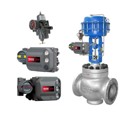
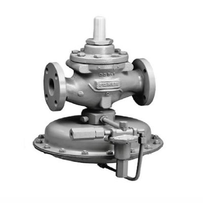
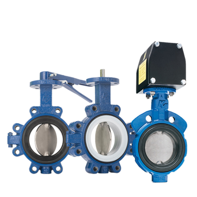
Control valves are at the heart of these loops, responsible for regulating the flow of fluids (such as gas, steam, water, or chemical mixtures) to compensate for load disturbances and keep the controlled process variables as close as possible to the setpoint. A complete control valve assembly typically consists of a valve body (containing fluid passages and regulating elements), valve internals (such as valve discs, valve plates, valve seats, valve cores, etc., which directly contact the fluid and regulate flow), an actuator (providing the driving force required to operate the valve), and various valve accessories (such as positioners, converters, supply pressure regulators, limit switches, etc.).
Fail-safe: The highest priority in industrial design
In the field of industrial automation, merely achieving functional control is insufficient; it is also necessary to consider the system's behavior under abnormal conditions, i.e., “fail-safe" design. Fail-safe refers to the system automatically entering a predefined, non-hazardous state when a fault occurs or the drive power is lost, thereby preventing or mitigating accidents.
Fail-safe design for control valves is an indispensable component of industrial production, particularly in the production and processing of high-value, hazardous materials such as crude oil, natural gas, and chemicals. It effectively prevents major accidents, such as in fuel pipelines, where safety shut-off valves automatically close upon detecting unsafe conditions, preventing fuel from entering the combustion chamber and thereby avoiding fires or explosions. Additionally, by promptly guiding the system to a safe state, economic losses caused by equipment damage and production interruptions can be minimized. More importantly, fail-safe mechanisms directly protect operators from potential hazards, which is the most fundamental consideration in all industrial designs. Furthermore, many industries have strict safety regulations and standards (such as SIL ratings) requiring critical equipment to possess specific fail-safe capabilities, making fail-safe design a necessary condition for compliance with regulations.
Xiangjing Company fully understands the importance of fail-safe design for control valves and is committed to providing high-reliability control valve products and solutions that comply with international safety standards. Through continuous technological innovation and strict quality control, Xiangjing aims to become a trusted partner in building a safe and efficient industrial future. For more information, please visit Xiangjing Company's official website .

Part One: Fundamentals of Control Valve Fail-Safe
This section will explore the core concepts of control valve fail-safe, including its precise definition, its critical role in industrial safety, and its relationship to international safety standards (such as SIL).
1. What is control valve fail-safe?
Control valve fail-safe refers to the automatic movement of the valve's shut-off element to a pre-determined position when the drive energy supply is interrupted (e.g., instrument air supply failure, power failure). This pre-set position must be the “safe" state necessary to protect the process and equipment. It is an inherent characteristic designed to address unplanned shutdowns or system abnormalities.
Fail-safe design is a core component of functional safety, with the objective of reducing risks to personnel, the environment, and property to an acceptable level. For example, in a reactor, if the cooling system fails, the cooling water valve should automatically open to prevent overheating and potential hazards. Conversely, if the fuel supply valve fails to close during a fault, it may result in continuous fuel leakage, leading to fire or explosion.
Timely transition to a safe state prevents equipment from continuing to operate under fault conditions and causing damage. Most importantly, fail-safe mechanisms directly reduce the risks faced by operators.
Fail-safe design is closely related to SIL (Safety Integrity Level). SIL is a discrete rating used to measure the reliability of safety functions and quantify the extent of risk reduction. A single component (such as a control valve) cannot have an SIL rating on its own; only a complete safety loop or safety instrumented system (SIS) can achieve an SIL rating. A typical safety loop includes sensors, evaluation and output units (such as a safety PLC), and automated process valves (including solenoid valves, actuators, and process valves). The fail-safe design of control valves is a critical component in achieving a specific SIL rating, ensuring that safety functions can be reliably executed in low-demand modes (where the safety system is activated no more than once per year).
Fail-safe design is a core aspect of risk management. Traditional control systems focus on efficiency and precision under “normal operating conditions." However, the complexity and potential hazards of industrial production dictate that behavior under “abnormal conditions" is more critical. The essence of fail-safe mechanisms is to anticipate and mitigate worst-case scenarios during the design phase, guiding the system to the “least dangerous" state. This is not merely a technical implementation but a concrete application of safety philosophy in engineering, reflecting a paradigm shift from “production efficiency first" to “safety first." This means that when selecting control valves, their fail-safe mode is not merely a technical parameter but a strategic decision made after a thorough assessment and understanding of the risks across the entire process. When procuring and implementing control valves, companies must prioritize fail-safe functionality as equally important as performance, and in certain critical applications, safety takes precedence over all other considerations.
2. Classification and Selection of Fail-Safe Modes
The fail-safe modes of control valves are primarily categorized into three types, each corresponding to specific application scenarios and safety requirements. Selecting the appropriate fail-safe mode is critical to ensuring the safe operation of the system.
Fail-Closed (FC) / Air-Loss-Closed (Fail-Closed)
When the drive energy (such as air supply or power) is interrupted, the control valve's shut-off element automatically moves to the closed position. This means that during a fault, the fluid passage is blocked. This mode is most commonly achieved through a spring-return actuator, where the spring's preload force pushes the valve to the closed position when air pressure or power is lost.
Typical application scenarios include:
- Fuel gas valves: In burner applications, safety shut-off valves must automatically close when unsafe conditions (such as power failure) are detected to prevent fuel (gas or oil) from entering the combustion chamber, thereby avoiding fire or explosion.
- Reactor feed valves: In chemical reactions, if the reaction becomes uncontrolled (such as a sudden increase in temperature), the feed valve should immediately close to stop material input, preventing the reaction from further escalating.
- High-pressure systems: In high-pressure fluid systems, fault closure prevents accidental leakage of high-pressure media, reducing risk.
Fail-Open (FO) / Loss-of-Pressure-Open (Fail-Open)
When the drive power is interrupted, the control valve's flow-restricting element automatically moves to the open position. This means that during a failure, the fluid passage is fully opened. This mode is also commonly achieved through spring-return actuators, but the spring configuration direction is opposite to the FC mode, ensuring the valve is pushed to the open position during a failure.
Typical application scenarios include:
- Cooling water valves: In reactors or other systems requiring cooling, if the cooling system fails or power is interrupted, the cooling water valve should automatically open to ensure continuous flow of the cooling medium, preventing equipment overheating.
- Relief valves/bypass valves: When system pressure becomes excessively high, relief valves or bypass valves automatically open to release pressure, protecting equipment and piping.
- Emergency venting: In certain processes requiring emergency venting, fail-open ensures the medium can be rapidly discharged.
Fail-Last (FL) / Fail-in-Place
When the drive power is interrupted, the control valve remains in the last position before the failure occurred. This mode typically requires additional locking mechanisms or energy storage devices to maintain the valve position. This is usually achieved through special positioners (with lock-in valves) or double-acting actuators combined with energy storage devices (such as air tanks or hydraulic locks). For pneumatic systems, air tanks can provide a short-term backup air source for double-acting actuators, enabling them to maintain or complete specific actions when the main air source fails.
Typical application scenarios include:
- Systems requiring manual intervention: In certain complex or sensitive processes, immediately fully opening or closing valves may lead to more severe consequences. Fail-safe operation allows operators time to assess the situation and manually intervene, safely bringing the system into a stable state.
- Maintaining the current state: In non-emergency scenarios where maintaining flow is necessary, such as when flow fluctuations have minimal impact on downstream processes, fail-safe operation can prevent unnecessary process interruptions.
- High-precision regulation: In circuits requiring high-precision regulation, fail-safe operation prevents valves from suddenly fully opening or closing when signals are lost, thereby reducing the impact on the process.
Selection Principles
The selection of a fail-safe mode is not arbitrary but is based on a comprehensive risk assessment of the specific process. Engineers must analyze which valve state (closed, open, or maintained) can minimize the risk of personal injury, equipment damage, and environmental pollution in the event of an energy failure. Additionally, factors such as fluid properties (flammable, explosive, corrosive), the dynamic response of the process, and interlocking relationships with upstream and downstream equipment must be considered. For example, for media that may cause hazardous accumulation, the default position is typically selected as fail-closed; for systems requiring continuous cooling or pressure relief, the default position is selected as fail-open. Adhering to relevant industry standards and regulations (such as API, NFPA, IEC 61508) is also critical, as these standards often provide recommendations or mandatory requirements for fail-safe modes based on specific applications.
The selection of fault-safe modes is the “first line of defense" in process safety design. The pre-set fault modes of valves determine the system's “default" behavior under worst-case conditions. This pre-set behavior must align with the inherent hazards of the process to ensure that, in the event of a fault, the system automatically enters the safest physical state. For example, the fuel valve FC prevents uncontrolled combustion, while the cooling valve FO prevents overheating explosions. This embodies the principle of “safety by design" rather than relying solely on post-incident remedies. It underscores the importance of conducting detailed Hazard and Operability (HAZOP) analyses and Safety Integrity Level (SIL) assessments of the process flow during the early stages of a project. Control valve suppliers such as Xiangjing Company engage in in-depth discussions with clients about their process characteristics when providing products, offering professional recommendations for fail-safe mode selection rather than merely selling standard products.
Part Two: Core Components for Achieving Fail-Safe Functionality
This section will provide a detailed explanation of the key components for fail-safe operation of drive control valves—actuators and valve positioners—and analyze their respective working principles, fail-safe mechanisms, advantages and disadvantages, and applications in industry.
1. Actuators: Driving Fail-Safe Actions
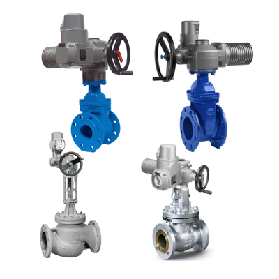
Actuators are the “muscles" of control valves, responsible for converting control signals into mechanical motion to alter the position of the valve's flow-restricting element. Their design directly determines the valve's behavior during a fault. Actuators are typically categorized into three main types: pneumatic, electric, and hydraulic.
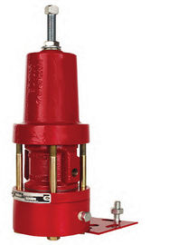
Pneumatic Actuators
Pneumatic actuators utilize compressed air (typically air) pressure to drive a piston or diaphragm, causing the valve stem to move forward and backward (linear motion) or rotate via a gear-rack mechanism. Gas pressure can be alternately applied to both sides of the piston (double-acting) or enter only one side and rely on a spring for return (single-acting).
Fail-safe mechanisms:
- Spring-Return: This is the most common and inherent fail-safe mechanism in pneumatic actuators. When the drive air source is lost, the pre-compressed spring force pushes the actuator to a pre-set safe position (fully open or fully closed),This design is simple and reliable, widely used in applications requiring a clear fail-safe state.
- Air Tank/Accumulator: For double-acting pneumatic actuators, when the main air supply fails, the connected air tank can provide backup compressed air, enabling the valve to continue operating or complete the pre-set fail-safe action within a specific timeframe. This is particularly useful for maintaining process operations or safe shutdowns over an extended period, such as ensuring that a control valve continues to operate during a specific timeframe following an air compressor failure, allowing for repairs or safe shutdown.
Advantages and Disadvantages:
- Advantages: Simple structure, lightweight, and relatively easy to install and maintain. The working medium is air, which is easy to exhaust, environmentally friendly, and cost-effective. Output force and operating speed are easily adjustable, with typically fast response times. High reliability and long service life.Fireproof, explosion-proof, and moisture-resistant, suitable for high-temperature environments. Can store energy, enabling centralized air supply and long-distance transmission.
- Disadvantages: Due to the compressibility of air, operating speed is easily affected by load changes, and low-speed stability is inferior to hydraulic cylinders. Output force is generally lower than that of hydraulic cylinders. Slow pneumatic signal transmission speed, unsuitable for complex systems requiring high-speed signal transmission. Requires a continuous supply of compressed air and regular maintenance to prevent leaks. Initial costs may be lower, but long-term operational costs (compressors, piping, maintenance) may be higher.
Industrial applications: Widely used in applications requiring fast motion and explosion-proof requirements, such as the petroleum and natural gas, chemical, food and beverage, and water treatment industries.
Electric Actuators
Electric actuators convert electrical energy into rotational or linear motion using motors (commonly stepper motors and servo motors) to control position, speed, torque, etc. Stepper motors achieve precise positioning through pulses, while servo motors achieve dynamic response through feedback control.
Fail-safe mechanisms:
- Backup Power/Capacitor: In the event of a main power failure, electric actuators can be equipped with a backup battery pack or supercapacitor to provide temporary power to complete pre-set fail-safe actions (such as driving the valve to the fully open or fully closed position). This mechanism ensures the final safety barrier in the event of a power outage.
- Mechanical Spring: Some electric actuators also incorporate mechanical springs, which use spring force to push the valve to a safe position in the event of a power failure. This design combines the precise control of electric power with the inherent fail-safe characteristics of springs.
Advantages and Disadvantages:
- Advantages: Provides accurate and repeatable positioning, making it ideal for automated tasks. High energy efficiency, especially in static load applications where less energy is consumed. Low maintenance requirements, fewer parts, and no fluid systems involved. High versatility, capable of adapting to various environments, and easy to program for complex motion patterns. Quiet operation. Capable of achieving high-precision positioning and adjustable motion speeds. Rotational speed is unaffected by load variations and is independent of power supply voltage and frequency. Capable of remote control.
- Disadvantages: Cost is typically higher than pneumatic actuators. Control systems are complex, requiring specialized knowledge for installation and maintenance. Environmental resistance (e.g., waterproofing, dustproofing) may be lower than pneumatic components. Output force is relatively small, unsuitable for heavy-duty tasks. Dependent on a stable power supply and may not be suitable for explosive environments (unless specially designed). Cycle time may be slower than pneumatic systems.
Industrial applications: Suitable for scenarios requiring precise control and flexible operation, such as robotic arm drives, conveyor belt adjustments, assembly lines, agricultural machinery, ventilation systems, solar systems, material handling, and cleaning equipment. Also widely used in power generation, water treatment, and pharmaceutical industries.
Hydraulic Actuators
Hydraulic actuators use pressurized hydraulic fluid (usually oil) to drive pistons or blades, converting fluid pressure into mechanical motion. The incompressibility of hydraulic fluid enables it to provide enormous force.
Fail-safe mechanisms:
- Spring-Return: Similar to pneumatic systems, hydraulic actuators can also incorporate springs to push the valve to a pre-set safe position using spring force when the hydraulic system loses pressure. This method is commonly used in emergency applications requiring rapid shutdown or opening.
- Hydraulic lock: By locking the hydraulic oil circuit, the actuator remains in its last position when pressure is lost. This is typically achieved through special valve designs (such as two-position, two-way solenoid valves), ensuring that the piston output rod is locked in place during power or signal interruptions to prevent system disruption.
Advantages and Disadvantages:
- Advantages: Capable of producing extremely high torque/thrust output, suitable for operating large, heavy-duty, or high-pressure valves. High-precision positioning enables accurate process control.Quick response to control signals, suitable for ESD (Emergency Shutdown System) and valve applications requiring rapid action. Robust and durable design with relatively low maintenance requirements and a long service life.The incompressibility of hydraulic fluid ensures smooth and stable motion.
- Disadvantages: Complex system requiring hydraulic pumps, reservoirs, piping, etc., resulting in high installation and maintenance costs. Risk of hydraulic fluid leakage, which may contaminate the environment or cause safety issues. High requirements for fluid cleanliness; fluid contamination may lead to malfunctions.
Industrial Applications: Primarily used in heavy-duty tasks requiring high force output and rapid response, such as oil and gas drilling platforms, hydroelectric power stations, large industrial machinery, and gas pipelines.
The fail-safe characteristics of an actuator are inherent properties, not additional features. Fail-safe mechanisms such as spring return, air reservoirs, and backup power sources are not added as extras on top of the actuator's basic functions, but are inherent properties that are considered and integrated into the design from the outset. For example, spring return utilizes potential energy, while air reservoirs utilize the compressibility of gas to store energy. These mechanisms are passively triggered in the event of energy failure, embodying the “passive safety" design philosophy. This means that when selecting control valves, one should not only focus on the actuator's driving capacity but also thoroughly understand whether its built-in fail-safe mechanisms meet the specific requirements of the process. Xiangjing Company provides detailed explanations of the fail-safe principles of different actuators when offering control valve solutions, helping customers select the most suitable products for their application scenarios and ensuring reliability under extreme conditions.
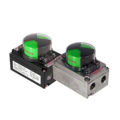
2. Valve Positioner: Precise Control and Fault Diagnosis
A valve positioner is a critical accessory in a control valve assembly. It not only ensures that the valve responds precisely to control signals but also plays a key role in enhancing the reliability of control valves and enabling advanced fault diagnosis.
The Function and Importance of Valve Positioners
The core function of a positioner is to supply pressurized air (or electricity) to the valve actuator, ensuring that the valve stem or valve shaft position precisely aligns with the control system's setpoint. This is achieved by comparing the actual valve position with the desired valve position and making necessary adjustments. The positioner overcomes factors such as valve stem packing friction, actuator lag, and unbalanced forces on the valve plug that affect precise valve positioning, thereby improving
the control accuracy and response speed of the control valve. Additionally, the positioner typically requires position feedback from the valve stem or valve shaft and transmits the valve position status to the upper-level system for process monitoring, fault diagnosis, or start/stop verification.
Signal Types and Feedback Mechanisms
Control valves receive signals from controllers to operate.
- Pneumatic Signals: Traditional process equipment uses pneumatic pressure signals (typically 20.7 to 103 kPa, or 3 to 15 psig) as control setpoints for control valves to move the valve from 0% to 100% position.
- Analog I/P Signal (4-20 mA): Most modern process equipment uses a 4 to 20 mA DC signal to regulate control valves. The I/P converter in the positioner converts the electronic current signal into a pneumatic pressure signal. The advantage of the 4-20 mA signal lies in its strong noise immunity, resistance to voltage drops, and self-monitoring capability (current below 3.8 mA or above 20.5 mA is considered a fault).
- Digital Signal: Digital valve controllers are microprocessor-based instruments that communicate with the control system via digital signals. Common digital communication protocols include HART® (overlaid on the traditional 4-20 mA signal), FOUNDATION™ Fieldbus, and PROFIBUS. Wireless technology also provides an alternative method for transmitting information.
- Feedback Mechanism: Positioners require position feedback from the valve stem or valve shaft to precisely control the valve.
- Mechanical feedback: In traditional pneumatic positioners, the position of the valve stem/shaft is compared with the position of the bellows receiving the pneumatic control signal via mechanical linkages and cams. This method has drawbacks such as high wear, low accuracy, and short lifespan.
- Electronic feedback: The microprocessor in a digital valve controller receives electronic feedback on the valve position. For example, Hall effect sensors are used to measure the magnetic field density on a permanent magnet array, enabling rodless, non-contact valve stem position feedback. This eliminates issues such as wear, corrosion, and vibration, significantly improving stability and reliability.
Valve Positioner Types and Their Role in Fail-Safe Operation
- Features: Receive pneumatic signals and output air pressure to regulate the actuator. Simple design, low cost, and reliable operation.
- Role in Fail-Safe Operation: Suitable for simple, robust operations, especially in environments without power supply or with explosion risks, as they do not produce sparks. They can provide sufficient force to close valves.
- Electro-Pneumatic Positioners / Analog I/P Positioners:
- Features: Receive electrical signals (typically 4-20mA), convert them into pneumatic signals via an I/P converter, and output them to the actuator. Compared to pure pneumatic positioners, they offer higher precision and resolution.
- Role in fail-safe operation: Combine the precision of electrical control with the robustness and safety of pneumatic operation. Suitable for industrial environments with both electrical and pneumatic infrastructure, as well as complex control strategies requiring higher precision.
- Digital/Smart Positioners:
- Features: Built-in microprocessor capable of receiving digital signals (e.g., HART, Foundation Fieldbus, Profibus) or 4-20mA signals. Offers high precision, high resolution, high reliability, and advanced diagnostic and communication functions.
- Role in Fault Tolerance:
- Advanced diagnostics: Capable of real-time monitoring of valve performance, detecting anomalies such as valve sticking, leakage, packing wear, and spring aging. This enables a shift from scheduled maintenance to predictive maintenance, significantly enhancing the system's overall fault-safe reliability.
- Self-calibration and remote monitoring: Many smart positioners feature self-calibration and remote monitoring capabilities, simplifying installation and commissioning, reducing maintenance costs, and enabling safe operation in hazardous areas.
- Contactless Feedback Technology: Utilizing non-contact feedback technologies such as Hall effect sensors eliminates wear, corrosion, and vibration issues associated with traditional mechanical linkages and contact-type potentiometers. This fundamentally improves the accuracy and reliability of valve position feedback, further enhancing fault-safe performance.
Positioners are key to the “intelligence" and “predictive safety" of control valves. Early positioners primarily addressed nonlinear issues in actuators to ensure precise valve response to control signals. With technological advancements, particularly in microprocessor and sensor technologies, digital positioners not only achieve precise control but also monitor valve health in real-time through built-in diagnostic algorithms and communication protocols. This enables systems to transition from “passively responding to faults" to “actively predicting and preventing faults," significantly enhancing fault safety levels. This evolution from “control" to 'diagnosis’ to “prediction" represents a significant trend in equipment management under the Industrial 4.0 framework. Investing in smart positioners is not merely about improvingthe control accuracy of control valves; it is an investment in the “health monitoring" and “preventive safety" of the entire process flow. The smart positioner solutions provided by Xiangjing Company can help customers achieve higher levels of fault diagnosis and predictive maintenance, thereby reducing the risk of unplanned downtime and improving the overall operational efficiency and safety of the factory.
Part Three: Advanced Fail-Safe Strategies and Technologies
In addition to fail-safe design for individual control valves, more advanced safety strategies are required in critical processes, such as redundant design, advanced fault diagnosis, predictive maintenance, and considerations for special operating conditions.
1. Redundant Design and Safety Loops
To further enhance system safety and availability, especially when handling high-risk or high-value media, redundant design is an indispensable strategy.
Types of Redundant Configurations
- 1oo2 (One-out-of-Two) Series Configuration: Two control valves are installed in series. If one valve or its control signal fails, the entire system shuts down to prevent further damage. This configuration significantly enhances safety, as any valve failure triggers a safe shutdown. It is commonly used in media conveyance lines requiring higher safety levels.
- 2oo2 (Two-out-of-Two) Parallel Configuration: Two control valves are installed in parallel. If one valve or its control signal fails, the system remains active and continues to operate. This configuration primarily enhances system availability, ensuring that the process is not interrupted in the event of a single component failure. It is commonly used in scenarios requiring high availability, such as cooling loops.
- 2oo3 (Two-out-of-Three) Voting Configuration: This configuration combines higher safety and availability. The system has three control valves, and the system only executes the corresponding action when two of the valves send the same signal. This allows testing the functionality of a single valve without activating the actuator, while the system can continue to operate safely even if a single valve fails. The 2oo3 functional module combines series and NAMUR technology to provide the highest level of safety and reliability, and allows maintenance during operation.
Application in Safety Instrumented Systems (SIS)
Redundant design is a critical component of Safety Instrumented Systems (SIS). SIS forms an independent protective layer through sensors, logic controllers, and final control elements (such as control valves), aiming to bring the process into a safe state when the Basic Process Control System (BPCS) fails. Redundant control valves ensure the final execution capability of SIS, meeting specific SIL level requirements.
Redundant design is an art of balancing safety and availability. Redundant architectures such as 1oo2, 2oo2, and 2oo3 are not simply about increasing the number of devices but involve strategic choices between “safety" (preventing hazards) and “availability" (maintaining operation) based on different process requirements. 1oo2 prioritizes safety over availability, 2oo2 prioritizes availability over safety, while 2oo3 seeks to strike the optimal balance between the two. This trade-off reflects the deep considerations in complex system design: how to achieve optimal risk management and operational efficiency within limited resources. This means that when selecting redundancy strategies, businesses must have a clear understanding of the risk level of their process operations, downtime costs, and safety requirements. Xiangjing Company, as a professional supplier of control valves, can provide products and technical support tailored to different redundancy architectures, helping customers design and implement the most suitable safety loops based on their specific needs, thereby achieving the optimal balance between safety and availability.
2. Fault Diagnosis and Predictive Maintenance
Having fault-safe mechanisms alone is insufficient. The ability to diagnose and predict potential faults in real time, thereby intervening before a fault occurs, represents a higher-level requirement for enhancing the reliability of control valve systems.
Diagnostic Functions of Intelligent Positioners
- Valve Sticking Detection: Monitors the deviation between valve position feedback and the setpoint to determine if sticking has occurred.
- Leak Detection: Monitors the appropriateness of output air pressure via pressure sensors to diagnose internal or external leaks.
- Packing wear diagnosis: Monitors changes in maximum friction force to determine the aging or hardening of the gland packing.
- Spring aging/tilting: Uses force balance diagnosis to detect abnormal conditions in the actuator spring.
- Air circuit diagnosis: Detects the severity of oil and water accumulation inside the positioner.
- Operating time/cycle count: Records valve operating data to assess wear levels.
Transitioning from scheduled maintenance to condition-based maintenance
Traditional maintenance models are based on time-based scheduled maintenance, which can lead to over-maintenance or under-maintenance. By leveraging real-time diagnostic data from smart positioners, factories can transition from time-based maintenance (TBM) to condition-based maintenance (CBM) and predictive maintenance (PdM). This means interventions are only performed when equipment condition indicates the need for maintenance, thereby optimizing maintenance resources, reducing maintenance costs, and minimizing unplanned downtime. Additionally, the adoption of non-contact valve stem position feedback technologies such as Hall effect sensors eliminates issues related to wear, corrosion, and vibration associated with mechanical linkages and contact-type potentiometers, fundamentally improving the accuracy and reliability of feedback and providing a data foundation for precise diagnostics.
Data-driven predictive maintenance represents a leap from “reactive" to “proactive" fault safety. Traditional fault safety is triggered passively after a fault occurs, while advanced diagnostic technologies use real-time data analysis to issue warnings at the “incipient" stage of a fault. This enables maintenance personnel to schedule repairs without disrupting production, transforming potential “fault safety trigger events" into “planned maintenance events," thereby avoiding the actual activation of fault safety mechanisms and reducing safety risks and downtime losses. This represents a major advancement in industrial automation, shifting from “reactive" to “proactive" approaches. Investing in smart positioners is not only about improving
control valve control accuracy but also about investing in the “health monitoring" and “preventive safety" of the entire process. Xiangjing Company's smart positioner solutions help customers achieve advanced fault diagnosis and predictive maintenance, thereby reducing the risk of unplanned downtime and enhancing the overall operational efficiency and safety of the plant.
3. Fail-safe considerations under special operating conditions
Under extreme or special operating conditions, fail-safe design of control valves requires additional consideration to address media characteristics and environmental challenges.
High-Temperature and Low-Temperature Environments
Extreme temperatures can cause valve components to expand, contract, become brittle, or soften, affecting normal valve operation and sealing performance. For example, high temperatures may cause the valve plug to seize, while low temperatures may impair actuator performance. Solutions include using an extended valve bonnet to protect the valve stem packing from extreme temperatures and selecting special high-temperature or low-temperature resistant materials to ensure reliability within the design temperature range.
Corrosive, high-viscosity media
Corrosive media can erode valve bodies and internal components, while high-viscosity media can adhere to valve stems, causing them to jam between the stem and body, making further operation difficult. Solutions include using corrosion-resistant materials (such as special alloys) and optimizing valve internal component structures to reduce media adhesion and scaling. V-port rotation
Control valves have advantages in handling solids.
Special requirements for emergency shutdown valves (ESD valves)
Emergency shutdown valves (ESD valves) are critical components in safety instrumented systems, with the primary task of quickly bringing the process into a safe state during emergencies. ESD valves typically require extremely high reliability, rapid closing speed, and low leakage rates. They are often designed as “fail-closed" or “fail-safe" to ensure immediate fluid cutoff when the drive energy is interrupted. To ensure the reliability of ESD valves, valve closure verification switches or valve leak detection systems are typically required. The closure verification switch activates after the valve is fully closed, ensuring that the fuel safety shut-off valve is completely closed before the purging and ignition cycle. The valve leak detection system monitors leaks by pressurizing the pipeline between two shut-off valves or determines individual valve leaks via pressure switch signals.
Fail-safe design must be deeply integrated with the operational environment. Simply selecting the correct fail-safe mode is insufficient, as the actual operating environment of the control valve (temperature, medium properties, pressure, etc.) can have a decisive impact on its fail-safe performance. For example, corrosive media may cause valve component failure, rendering the fail-safe mechanism inoperable.
Therefore, fail-safe design must be systematic, taking into account the challenges of the operating conditions from material selection, structural design, to diagnostic maintenance. This means that standard control valves may fail to meet safety requirements under extreme operating conditions, necessitating customized or specially designed solutions. Xiangjing Company, leveraging its extensive expertise in control valves, can provide professional selection recommendations and customized products tailored to various special operating conditions, ensuring that control valves reliably perform fail-safe functions even in the most demanding environments.
Part Four: Case Studies of Fail-Safe Control Valve Applications in Industry
Fail-safe design of control valves plays an indispensable role in many industrial fields. The following are several typical industries and their specific applications.
1. Oil and Gas Industry
In upstream oil and gas extraction, control valves in wellhead control systems must maintain precise flow regulation and emergency shut-off capabilities under extreme pressure, corrosive environments, and temperature fluctuations. Key functions of wellhead control valves include throttling control, pressure regulation, and emergency shutdown.
In oil and gas pipeline transportation, control valves are used to regulate flow, pressure, and temperature. Emergency shutdown valves (ESD) can quickly close when unsafe conditions are detected, such as pipeline ruptures or abnormal pressure, to prevent the leakage of high-value and hazardous substances, thereby avoiding environmental pollution and major safety accidents. In burner applications in refineries and chemical plants, fuel gas valves typically require “fail-closed" functionality to ensure that fuel supply is immediately cut off in the event of a power outage or signal loss, preventing fires and explosions.. Industry standards typically require the installation of two directly connected shut-off valves to provide redundant protection.
2. Chemical and Pharmaceutical Industries
Precise temperature and pressure control are critical in chemical reactors. For example, cooling water valves are often designed as “fail-open" to ensure that cooling water continues to flow in the event of a cooling system failure, preventing reactor temperature runaway and potential explosions. Feed valves are often designed as “fail-closed" to immediately cut off material supply in the event of a runaway reaction.
The chemical and pharmaceutical industries frequently handle corrosive, flammable, explosive, or toxic media. The fail-safe design of control valves ensures that hazardous media can be safely isolated or directed to a safe area in the event of a leak, abnormal pressure, or system failure. For example, control valves used for high-viscosity media require special design to prevent medium adhesion causing valve sticking, which could impair fail-safe operation. In pharmaceutical production, precise flow control and emergency shut-off capability are critical for product quality and production safety. The fail-safe characteristics of control valves ensure accuracy and repeatability in processes such as mixing, reaction condition control, and product filling.
3. Water Treatment and Power Industry
In water treatment plants, dams, and irrigation networks, control valves are used to regulate water flow, pressure, and liquid level. Fail-safe valves ensure that in the event of abnormalities in the water supply system, they can prevent excessive consumption, balance flow distribution, or prevent flooding in emergencies. For example, in the Harbin Mudanshan water supply pipeline project, DN1600 VAG piston valves were installed to control water pressure and flow and compensate for altitude pressure differences.
In power plants, control valves are used to regulate critical processes such as steam flow, cooling water, and fuel supply. Control valves in cooling systems are typically designed as “fail-open" to ensure continuous cooling water flow in case of pump failure or pipeline blockage, preventing equipment overheating. Hydraulic actuators, with their high torque output and rapid response capability, are commonly used to operate large, heavy-duty, or high-pressure valves, such as in hydroelectric power stations and gas pipelines.
Industry characteristics determine the focus of fail-safe strategies. While the core principles of fail-safe are universal, different industries have significant differences in their requirements and priorities for fail-safe. For example, the oil and gas industry prioritizes explosion and leakage prevention, so FC valves and redundant shut-off systems are core; the water treatment industry may prioritize water supply continuity and flood prevention, so FO valves and flow control valves are more important. This variability requires control valve suppliers to possess cross-industry technical understanding and customized solution capabilities. This means that the sale and application of control valves are not a one-size-fits-all approach but require a deep understanding of the customer's industry background and specific process requirements. As a professional control valve solutions provider, Xiangjing Company should emphasize its extensive experience and customized capabilities across multiple industrial sectors to provide customers with tailored fault-safe solutions, thereby enhancing its market competitiveness.
Part Five: Xiangjing Company's Contributions and Solutions in the Field of Control Valve Fail-Safe Technology
Xiangjing Company, official website, as a leading enterprise in the control valve industry, has always adhered to the philosophy of “safety first, innovation-driven," dedicated to providing global industrial customers with outstanding control valve products and comprehensive fail-safe solutions.
Xiangjing Company has been deeply involved in the control valve industry for many years, boasting a professional team composed of experienced engineers, R&D personnel, and industry experts. The company focuses on the design, manufacturing, testing, and application of control valves, accumulating deep technical expertise and extensive practical experience. Xiangjing Company understands the critical role of control valves in modern manufacturing and views them as an essential component in enhancing efficiency, safety, profitability, and environmental protection capabilities.
Xiangjing Company offers a comprehensive range of control valve products, including various valve bodies, valve internals, actuators, and valve accessories, to meet the diverse needs of industrial applications. The company's products incorporate fail-safe design principles from the outset:
- Diversified actuators: Xiangjing Company provides high-performance pneumatic, electric, and hydraulic actuators, and offers various fail-safe options such as built-in spring return, backup power supply, or hydraulic lock, tailored to different application scenarios, ensuring that valves can reliably move to pre-set safe positions in the event of power failure.
- Smart valve positioners: Xiangjing Company provides advanced digital/smart valve positioners that not only ensure precise control of control valves but also integrate comprehensive diagnostic functions to monitor valve health in real time, such as detecting valve sticking, leakage, or packing wear. This enables customers to implement predictive maintenance, addressing potential issues before they escalate, thereby significantly enhancing the system's fail-safe reliability.
- Customized Valve Internals: For special operating conditions such as high temperature, low temperature, corrosive, and high-viscosity media, Xiangjing Company provides customized valve internal design and material selection. For example, V-port rotary control valves have significant advantages in handling solids, ensuring that control valves maintain stable performance and reliable fail-safe operation even in harsh environments.
Xiangjing Company's fail-safe technology advantages are reflected in:
- Compliance with international safety standards: Some of Xiangjing Company's control valve products and solutions can meet international safety standards (such as IEC 61508 SIL certification), fulfilling customers' high requirements for functional safety.
- Full lifecycle services: The company not only provides high-quality control valve products but also offers full lifecycle services from selection consulting, solution design, installation and commissioning to post-installation maintenance and fault diagnosis. Xiangjing Company's expert team can provide professional advice on fault-safe mode selection and system integration solutions based on customers' specific process requirements and risk assessments.
- Reliability and long service life: Xiangjing Company's products are renowned for their exceptional manufacturing processes and strict quality control, ensuring high reliability and long service life under various harsh operating conditions, thereby reducing customers' operational costs and maintenance frequency.
Xiangjing Company has successfully provided safe and reliable control valve solutions for clients in multiple industries, including petrochemicals, power generation, water treatment, and metallurgy, helping them improve production efficiency and ensure operational safety. Xiangjing Company looks forward to collaborating with more enterprises to jointly address challenges in the field of industrial automation.
To learn more about Xiangjing Company's innovative technologies and outstanding products in the field of control valve fail-safe solutions, please visit the company's official website:www.shgongboshi.com .
Conclusion: Future Outlook for Fault-Tolerant Control Valves
Fault-tolerant design of control valves is an indispensable cornerstone of modern industrial automation. It not only affects production efficiency and product quality but also directly impacts the safety of equipment and personnel. From traditional spring-return actuators to intelligent digital positioners, fault-tolerant technology for control valves is continuously evolving to adapt to increasingly complex industrial environments and higher safety standards.
Looking ahead, the future of fail-safe control valves will exhibit the following trends:
- Intelligence and Predictive Capabilities: With the development of the Internet of Things (IoT), big data, and artificial intelligence technologies, future control valves will become increasingly intelligent. Smart positioners will not only execute control functions but also serve as “health monitoring centers," utilizing real-time data analysis and machine learning algorithms to predict potential failures and enable more precise predictive maintenance, thereby intervening before failures occur and minimizing risks.
- Higher Integration and Modularity: To simplify installation, reduce costs, and enhance reliability, control valve components will trend toward higher integration and modular design. Fail-safe functions may be more tightly integrated into the valve body or actuator, reducing external connections and minimizing potential failure points.
- Wireless and Remote Management: Wireless communication technology will become more widespread, enabling remote monitoring, diagnosis, and operation of control va

 Your message must be between 20-3,000 characters!