Control Valve Vibration in the Chemical Industry
In the chemical industry, control valves are widely used, and for the vibration of the control valve, some friends are not very well understood.
Control valve vibration refers to the phenomenon of rapid closing and opening of the valve during operation, indicating that the control valve is unable to remain stable in an appropriate position to maintain the intended process conditions.
This condition causes the process variable in a closed-loop system to fluctuate around its set point.

The causes of vibration may include the following:
- Controller problems: An improperly set controller or a failure of its internal components may result in an unstable control signal, which in turn may cause the valve to vibrate.
- Failure of control valve components: Wear or damage to specific components of the valve (such as spools, seats, or actuators) may also lead to vibration phenomena.
- Influence of operating method: Sometimes, even if the hardware itself is not defective, an inappropriate operating method or process design can trigger vibration.
Persistent valve vibration not only impairs the performance of the gland seal, it can also lead to significant deviations from the desired set point, affecting productivity and product quality. Therefore, it is critical to accurately identify the root cause of vibration in order to implement the necessary corrective actions to resolve the vibration problem and improve the overall performance of the control loop.
This article will delve into the various potential factors that cause valve vibration and how they are diagnosed, with the goal of helping readers better understand and deal with this common but complex industrial control challenge. By understanding this information, engineers and technicians can more effectively maintain and optimize their control systems to ensure the smooth operation of production processes.
What causes valve vibration?
- Control loop problem
Switch the controller mode from auto to manual and evaluate the response in the usual way to determine if the problem is within the loop.
If the oscillation stops, the loop is faulty. These problems usually occur in non-linear processes. Due to hysteresis effects, “hunting" may also occur. The result is that the process loop behaves sluggishly.
The controller is not configured to solve this mechanical problem. Stuck control valves caused by loop problems can be resolved by properly adjusting the controller. If this is not stated in the manual, it may be due to other causes, such as actual differences in process variables, valve sizing, etc.
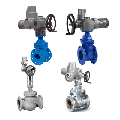
- Control valve size
The controllability of the valve is greatly affected by the size of the control valve. The coefficient of flow (abbreviated Cv) is the amount of water that can pass through a fully open valve at 600°F with a pressure drop of 1 psi.
The Cv is determined by the valve design and remains constant. Even control valves of the same size may have different Cv values if the body style or valve internals are different. The problem of control valve sizing becomes apparent when the total process gain is low or very high. Control valve sizes are often selected based on the need for future flow increases, which can result in the selected valve size being slightly larger than the current application requirements, which can affect control accuracy.
Valves that are too large can result in excessive opening and closing, causing seizing, packing damage and inaccurate control. Conversely, valves that are too small require a large pressure drop to maintain proper flow and may lack the necessary capacity, increasing pump pressure and raising the risk of cavitation. Cavitation and flashing are the main problems causing damage to the internal parts of the control valve, which in turn leads to fluctuations in process control.
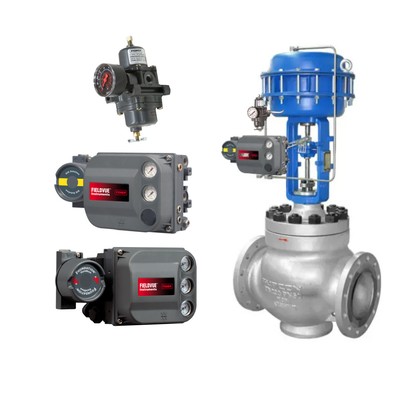
- Control valve positioner
In order to keep the control valve actuator in the equilibrium position required to control the process variables, the valve positioner is realized by regulating air pressure.
It has a spool to control airflow, but prolonged use or dust particles in the air may cause the spool to wear out, causing it to become stuck in a particular position, resulting in an abnormally high air pressure. Once the air pressure rises, the spool releases from the stuck position, triggering an overshoot that results in an unstable valve position, loss of effective control of the valve, and deflection.
The valve positioner may be exposed to high temperatures due to radiant heat from the surrounding process tanks, which can also be a factor in the positioner causing the control valve to stall, potentially leading to damage to the positioner seals and piping. The positioner utilizes a feedback link to detect the actual position of the valve to adjust the output.
If the feedback link fails, for example due to fluid forces or friction, the valve may not operate correctly. Modern intelligent positioners have the unique ability to recognize such deviations.
- Static friction during valve travel
When a valve encounters static friction (i.e., stalling), it stops moving at a specific position and requires additional force to restart. The cause of this phenomenon may be hardened gland packing or viscous flow within the spool.
When the applied force is sufficient to overcome the point of stall, the valve moves into the overshoot position, causing the process variable to exceed the setpoint. This stall can be observed by monitoring the relationship between the controller output and the process variable.
The valve actuator should be properly sized and the torque on the gland seal should be within acceptable limits to avoid stalling.
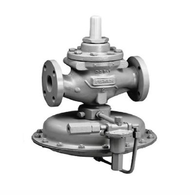
- Hardware defects
In addition, wear inside the spool may cause the valve to stall, preventing the valve from closing completely. Damage to the spool can cause a control valve to lose control in the high operating range.
In control valves, gland packing is used to prevent process media from leaking out of the valve body. If damaged, it can lead to leakage at the bonnet, threatening the safety of the working environment. Leaks in the valve actuator are another factor that can lead to valve “hunting".
The valve stem is initially precisely positioned by the valve positioner, but due to leakage, the stem will continue to move, forcing the positioner to repeatedly adjust the output, resulting in an infinite search for the stem position. This is one of the common tailing phenomena for control valves under steady-state control signals.
How to stop valve vibration?
Analysis and Diagnosis of Oscillation
Loop problems or other influences can cause control valves to oscillate. Determine the source of the problem by switching the controller to manual mode and watching to see if the oscillation stops. If the oscillation stops, it indicates that the problem is due to a problem in the loop itself, which can be resolved with appropriate adjustments.
Internal oscillations may be caused by improper adjustment or machine malfunction. If the valve still exhibits erratic behavior in manual mode, the problem may originate from a damaged valve assembly or a change in process parameters.
Sticking and positioner overshoot are the most common causes of control valve sticking. The output response of the valve in the presence of a sticking phenomenon can be clearly demonstrated by means of a graph.
What are the main causes of control valve sticking?
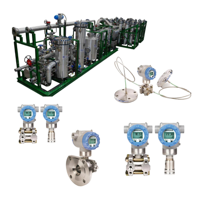
To determine whether control valve sticking is due to improper controller adjustment or mechanical failure of the control valve itself, it is recommended that the controller output be temporarily bypassed, constant pressure supplied to the control valve actuator, and the output response observed.
Linear potentiometers (position transmitters) are used to detect stem movement, while pressure transducers (smart positioners) are used to measure the output pressure of the positioner. By connecting these sensors to a data acquisition system and visualizing this data using monitoring software (such as Labview), a graph of stem travel versus controller output can be generated.
What is the main cause of a stuck control valve?
The microcontroller receives input signals from the controller setpoint and pressure sensors. When a pressure deviation from the setpoint is noted, it is considered “hunting" behavior if this deviation occurs more than five times. In this case, the output of the controller is isolated and the current-to-pressure converter (I-P converter) automatically generates a pressure corresponding to the setpoint and provides it as input to the control valve positioner. Check the deviation again after a few seconds.
If the deviation is found to be reduced, the control valve and its accessories are not faulty.
Therefore, a special adjustment of the controller circuit is required. However, if the valve is still faulty, the internal parts may be damaged or stuck due to the gland seal. With the aid of a graph with dead zones, the exact location of the sticking can be easily found.
In the case of persistent beating but no evidence of a dead zone, the vibration is most likely occurring due to damage to a component such as the spool. This method can also help determine if the trapping phenomenon is present throughout the entire control range or is limited to certain specific operating intervals.

 Your message must be between 20-3,000 characters!